Some updates on V2

Sorry for not updating this for a while but since this is a sold head the progress is subject to the new owners available time.

This is the head with all the initial machine work done. I pressure tested the casting at 75 psi and it held fine.

img_1284


img_1285


I messed up and spot drilled the wrong hole pattern for the exhaust flange. The head is 356 heat treated to T6 so I wasn’t too interested in putting any unnecessary heat on it by welding them up. They are behind the exhaust flange anyway.

img_1287


The owner of the head did his own port cleanup. He is going to finish blending in the port match after the valve work is done.

img_1289


The head has been vacuum resin impregnated and is at the machine shop having the valve work done.

Started Machining V2

Got V2 back from radiology and it looks great. The changes I made to the gating and risers solved the bad shrink porosity I had in the front.

Got it all set up in the mill.

IMG_1194

If it aint crashing it’s clearance.

IMG_1195


Got the bottom side completely finished.

Surfaced, head bolt holes and dowels, water passages.

IMG_1196


Chamber roughing pass.

IMG_1197


IMG_1198

Finish pass completed.


IMG_1201

The chamber size is 45cc’s. This should yield a 10.8:1 CR on the build without changing the pistons.


Cam shafts and cam towers.

The head has been held up waiting on radiology testing so I’ve been working on other components.

IMG_1175

So I bit the bullet and decided to try my hand at making cam towers. They are machined out of 6061 T6 and match the factory specs except for the cam bore size. I opened the bore up to 1.25″ since I have a nice Sunnen hone and the smallest it will go is 1.25″. I increased the cap thickness accordingly.

I also changed the design on the cams a bit. The front is the same as a KA24 and matches the cam gear. I’m doing away with the adjustable hubs and replacing them with multiple dowel holes and a drilled gear. With this combo I’ll be able to have 1.25 degrees of adjustment with 2 dowel pins. Stronger, cheaper, better.

I’m also incorporating the thrust bearings into the cams and having Crane grind them to size when they do journal #1. The main reason for this was it let me increase the diameter of the camshaft at the end. Mucho stronger.


IMG_1180

I made a fixture plate to bore all 7 towers at a time but for right now I’m only doing one at a time. I bore each opening without moving the table switching the towers in and out. This way the bores are all in line. Went a lot faster than I thought it would.

IMG_1173

IMG_1172

The bores came out wicked smooth. Much better than the used towers I’m running on mine.

IMG_1177

IMG_1178


And then there were two

Sorry I haven’t posted any new content lately. I’ve been super busy.

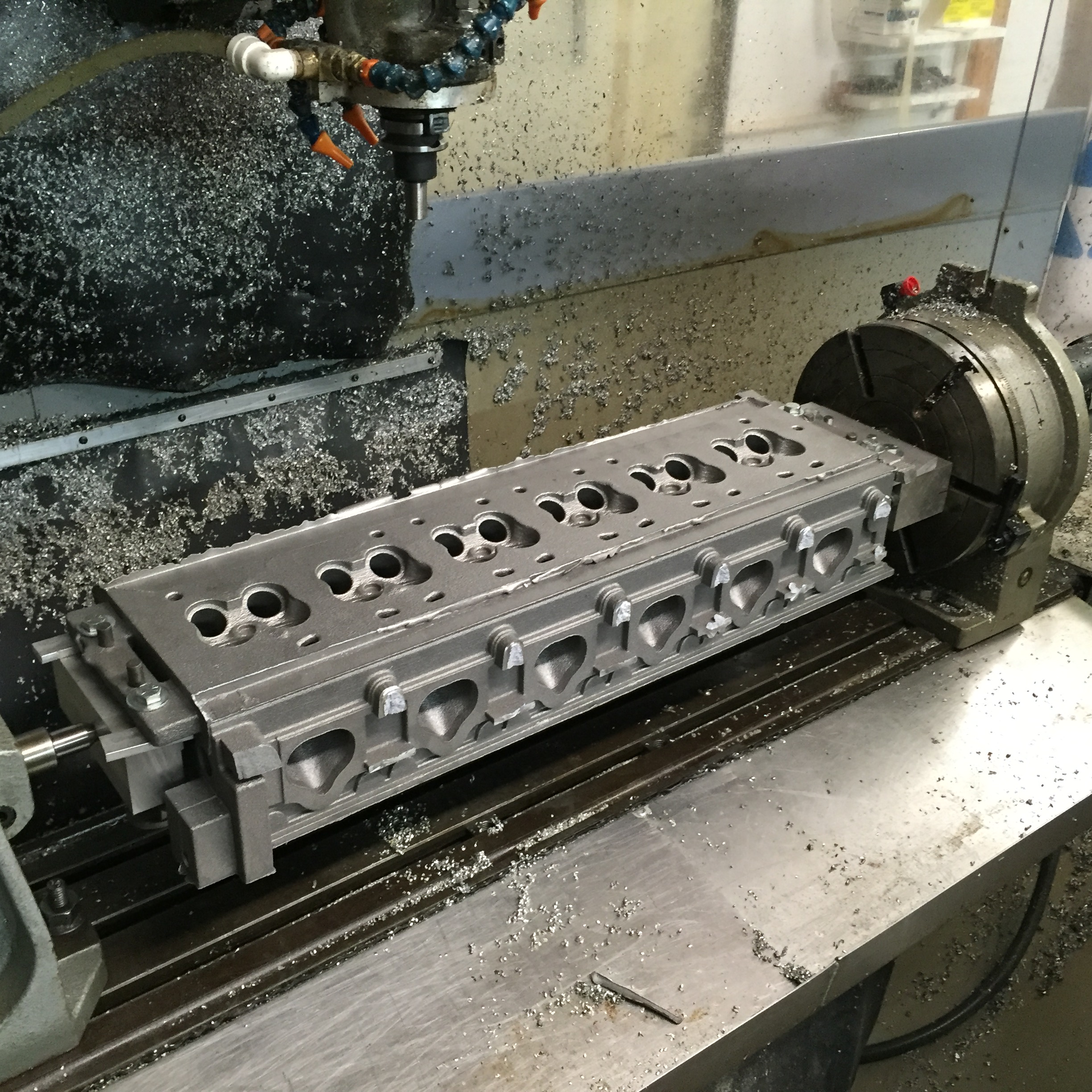
I did manage to get this done though.

IMG_1063

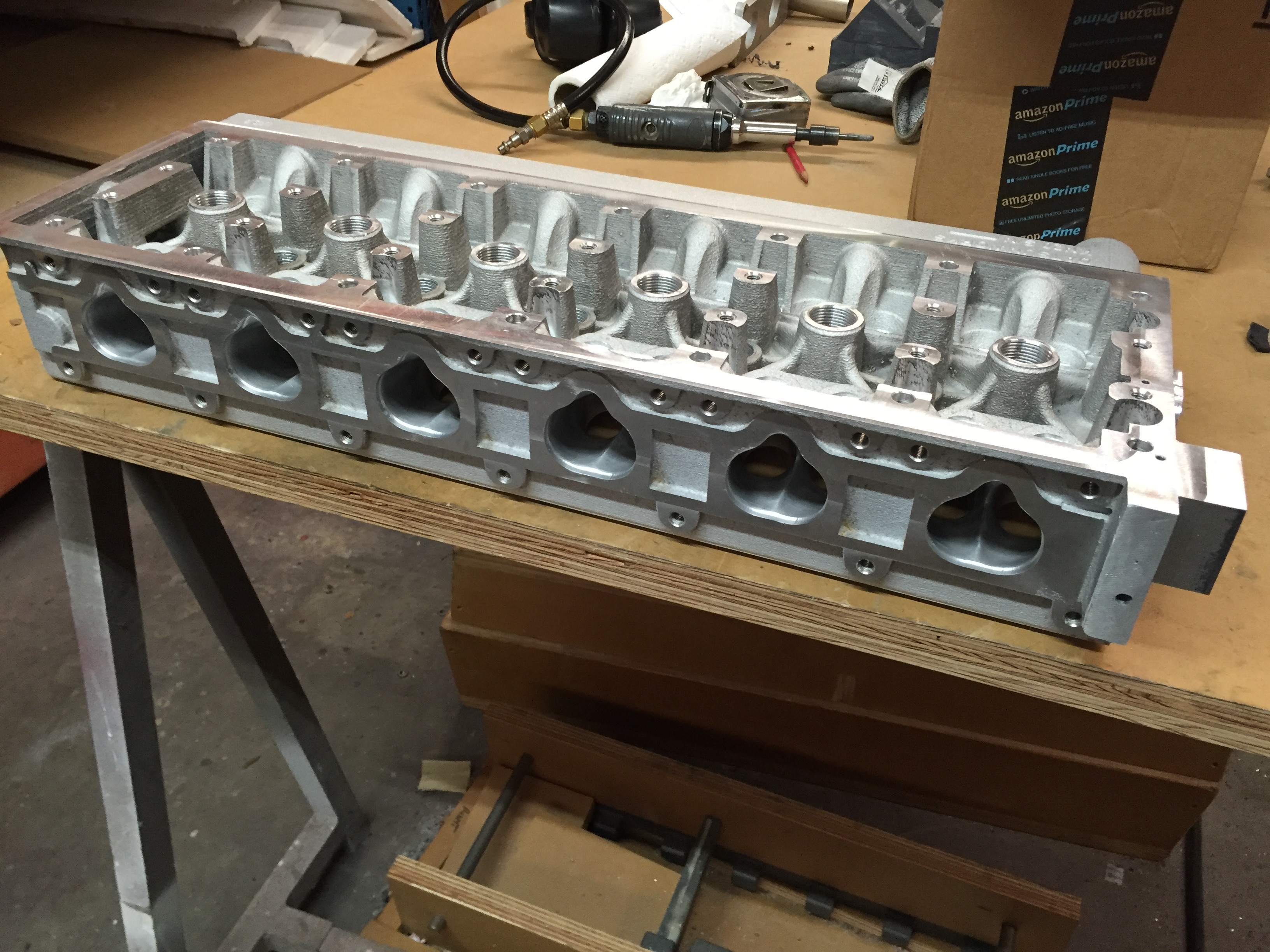
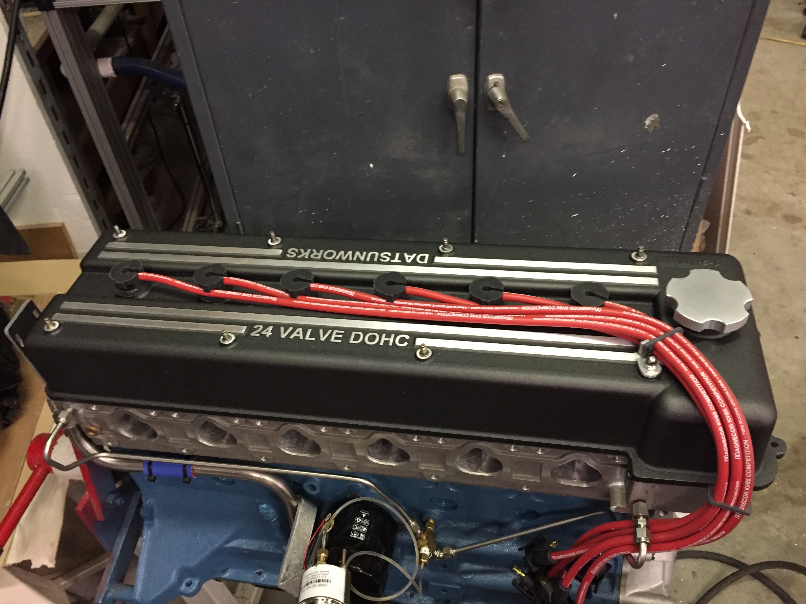
This is V2 of the head and most likely the production version. The major changes are:

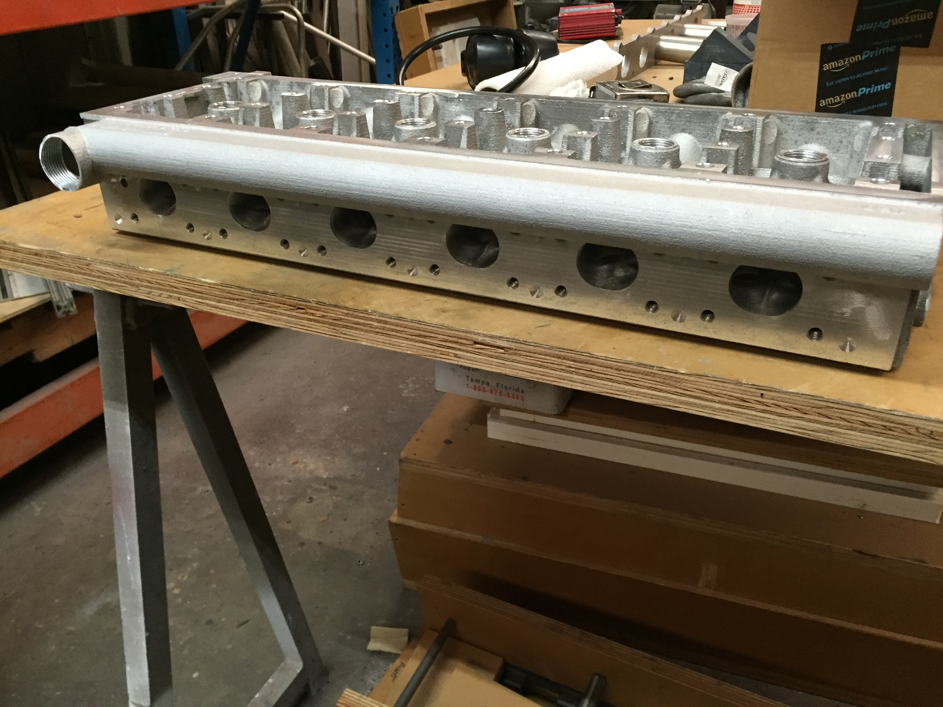
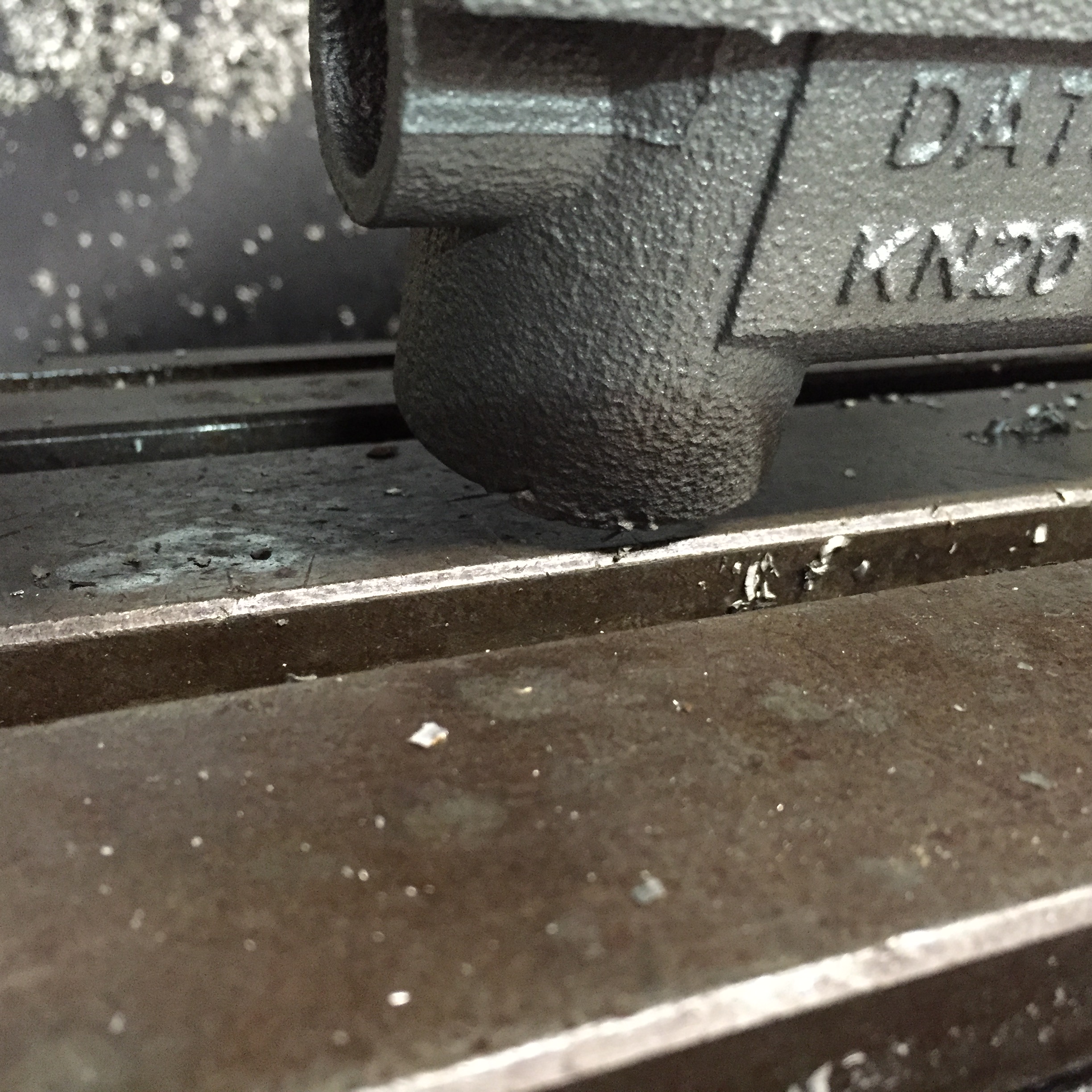
I now have the water exiting over each exhaust port and flowing into a central tube. This is the same way OSG and others do it. I opted to try and make it part of the casting to save the cost of making a separate water manifold. Plus it’s a really good example of how versatile 3D sand printing is. The outlet is designed to be  tapped   1 1/4″ NPT but you could easily weld something on instead.

I added a rear sump for the oil to drain into the stock oil return. This will do away with the external drain tube that I’m currently using.

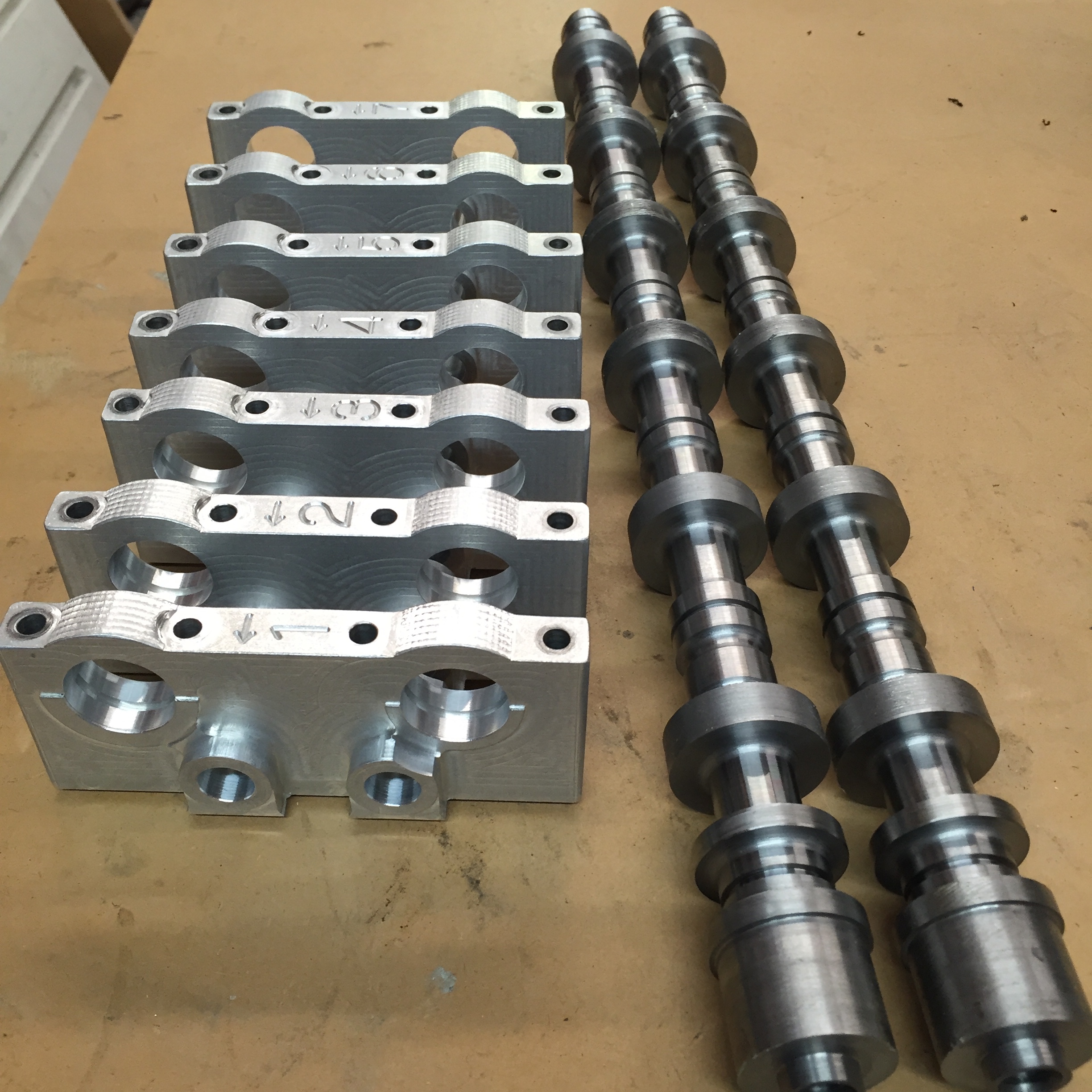
I bridged the rear cam tower boss and added a connecter between the back of the head and the tower. This is where the rear oil feed will go.

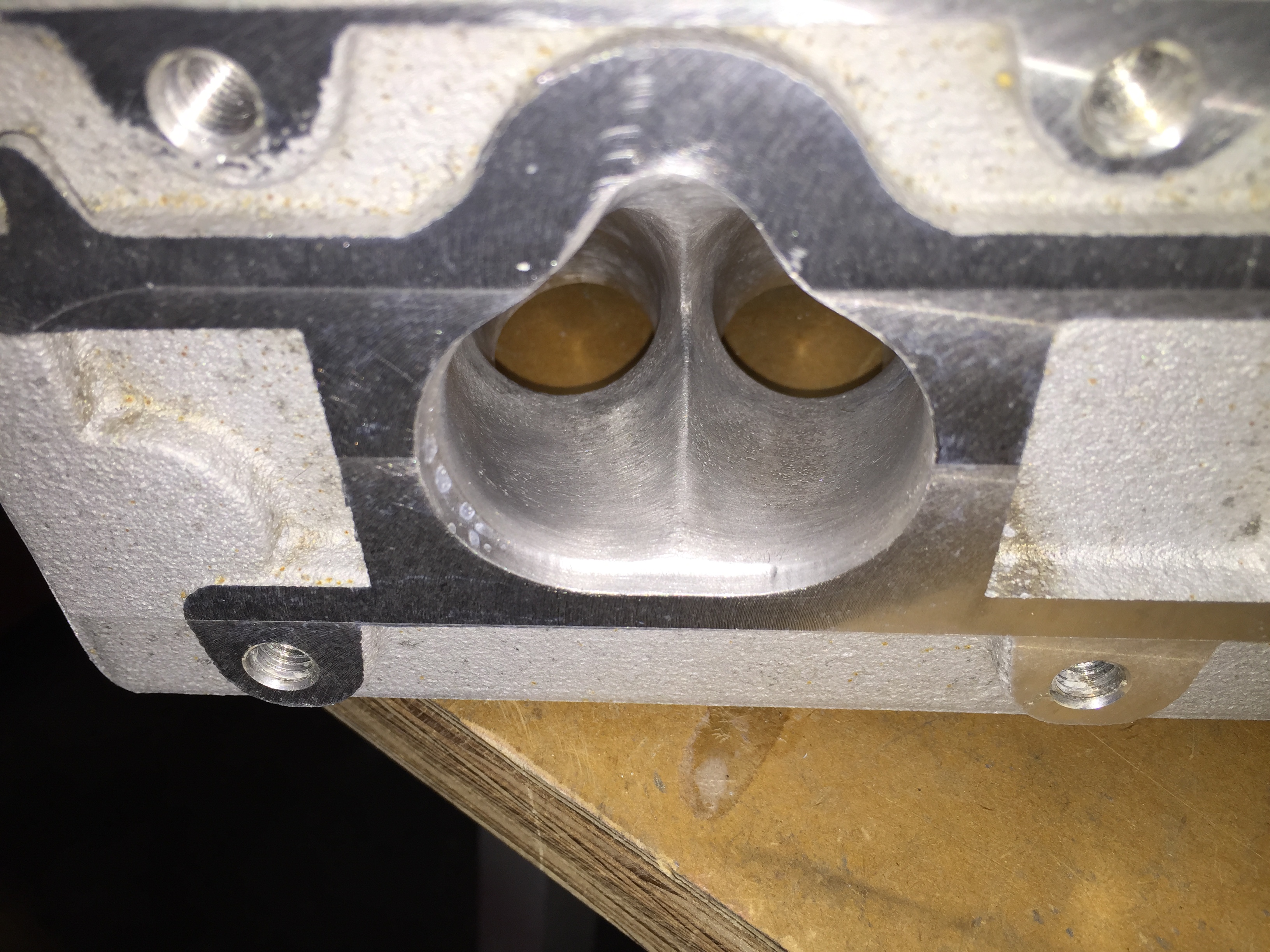
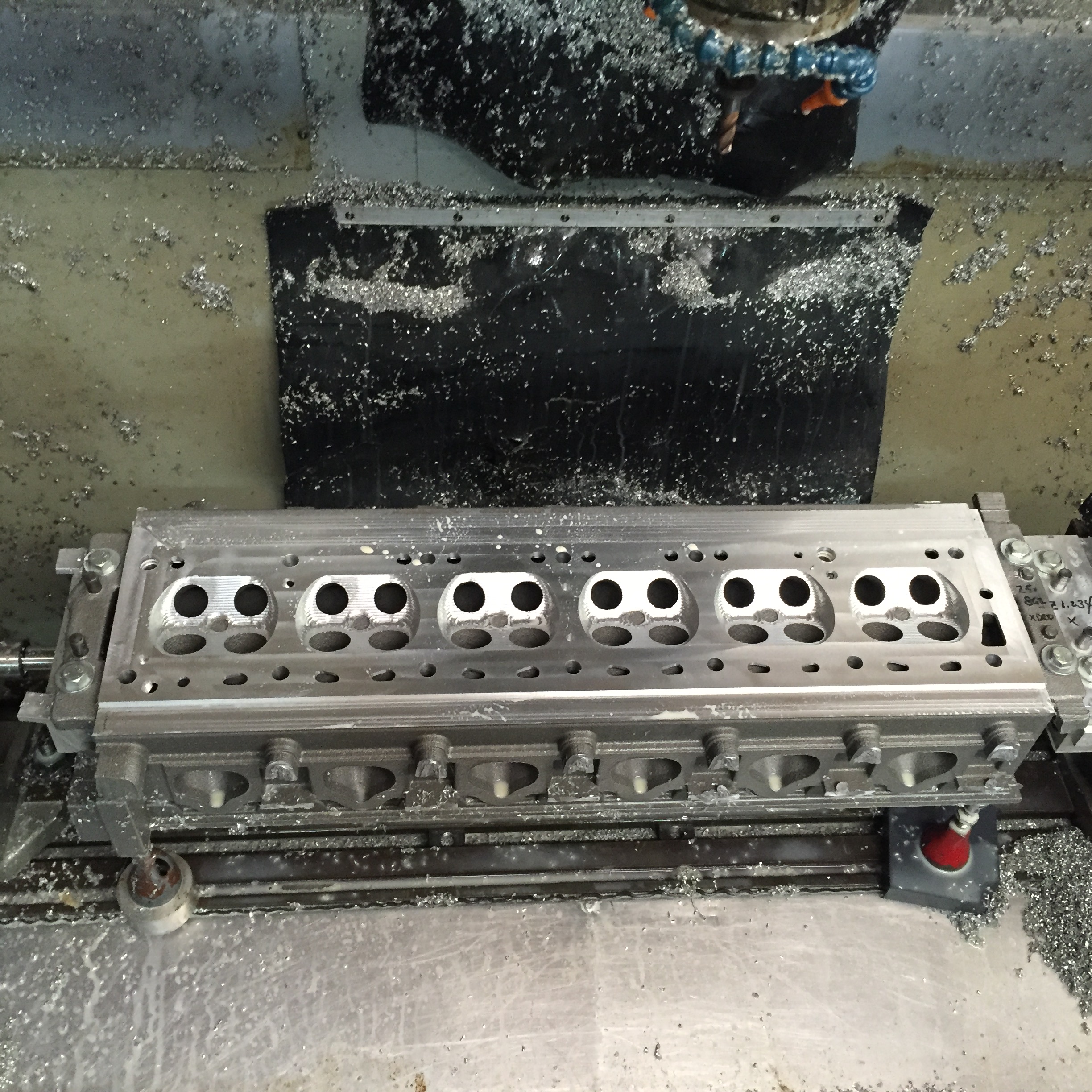
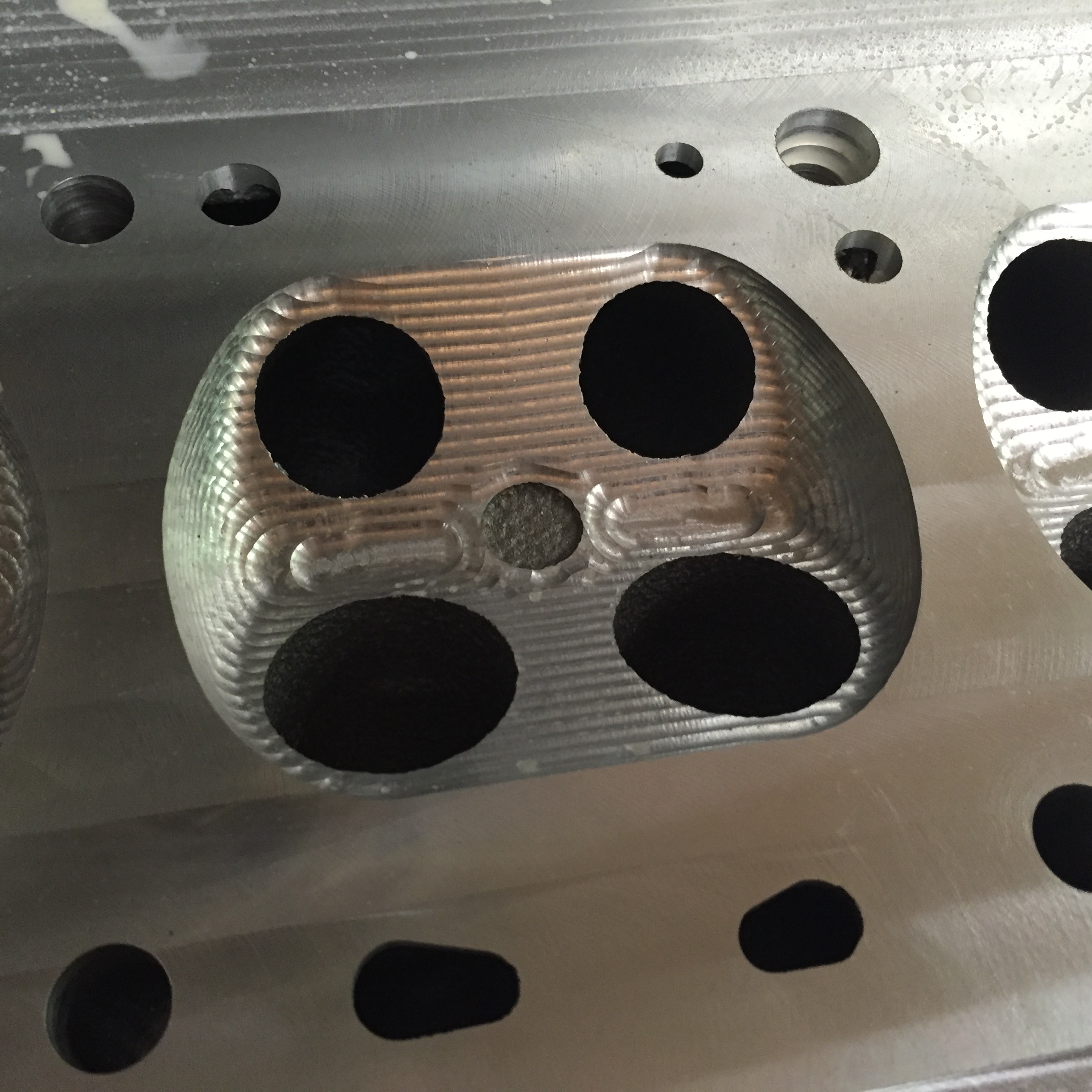
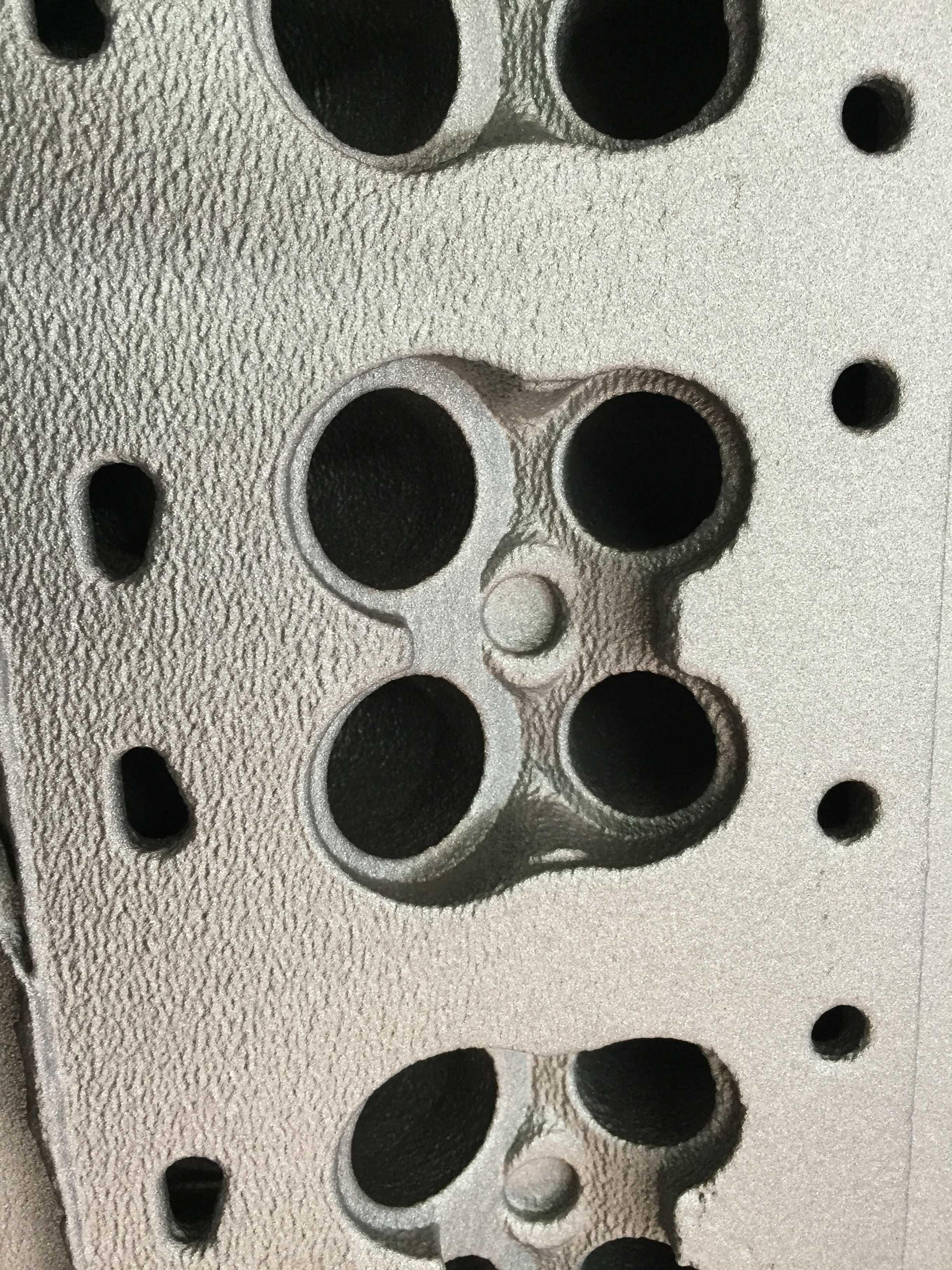
I redesigned the combustion area so that it has plenty of meat for those who want to get creative.

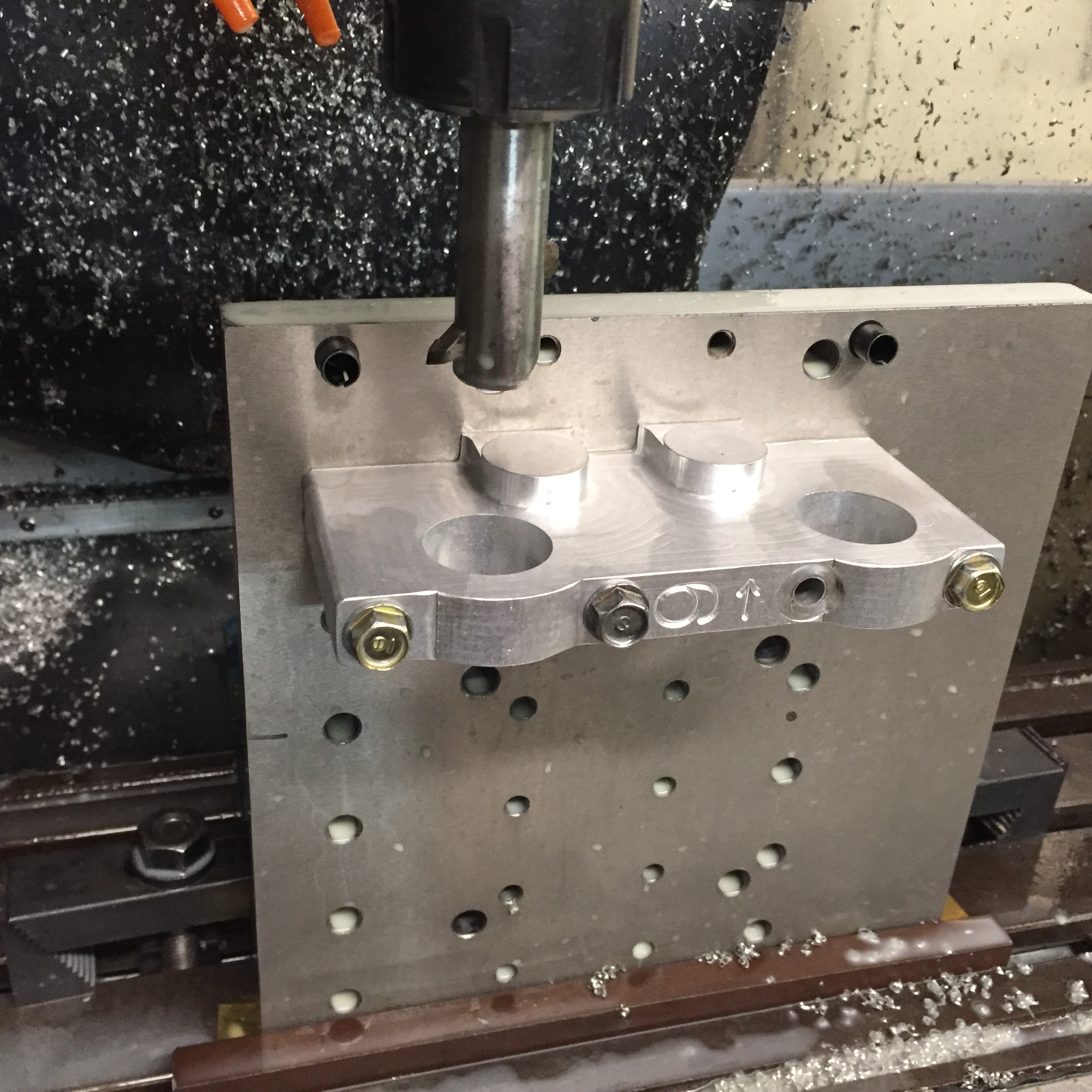
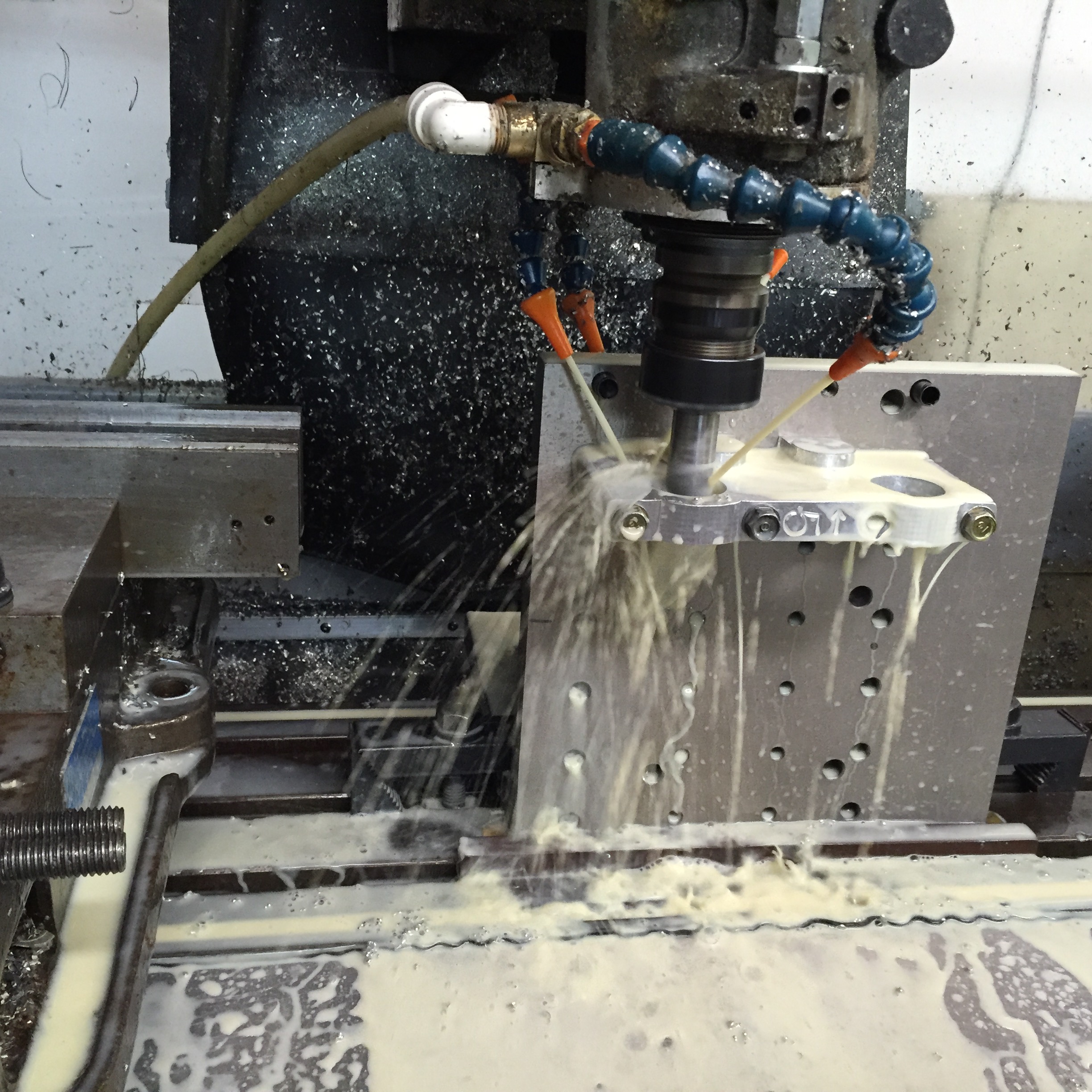
There are a ton of little changes that reflect things I ran into during the machining of the prototype.


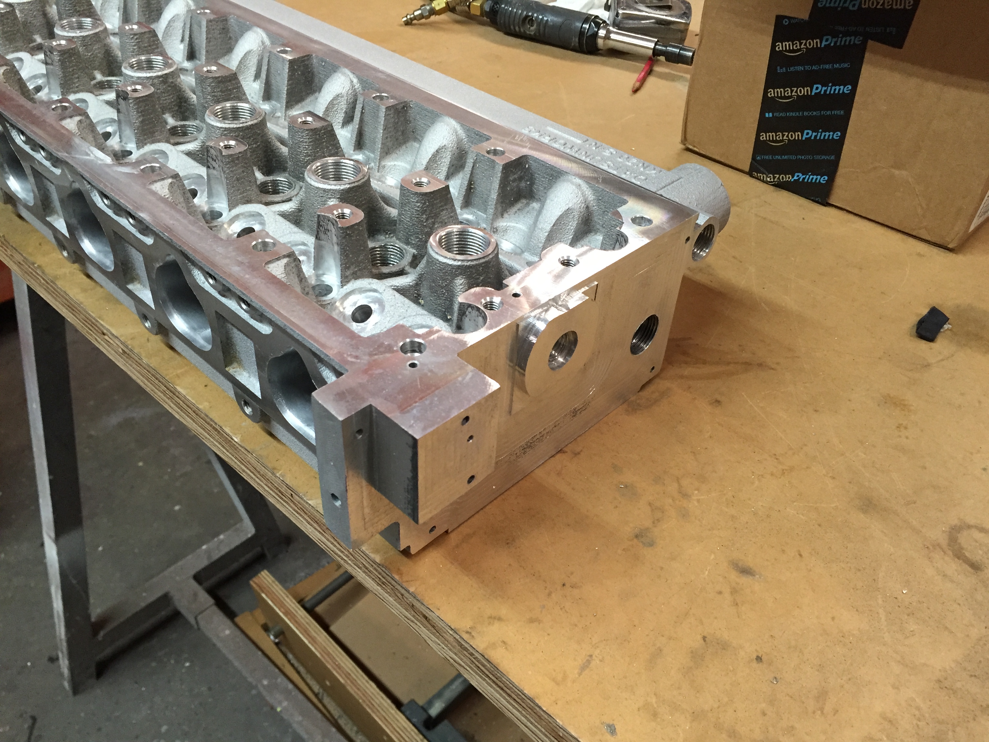
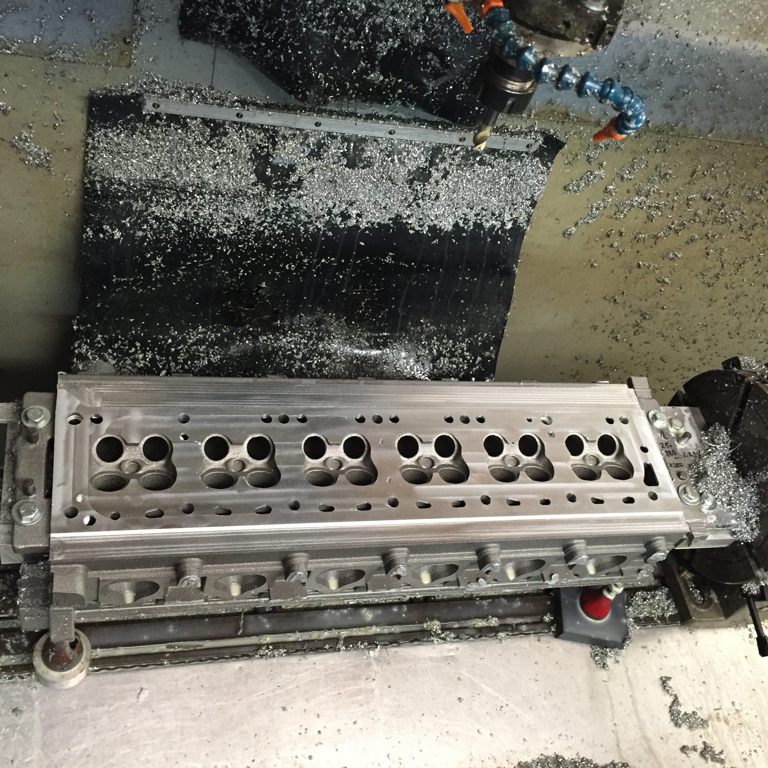
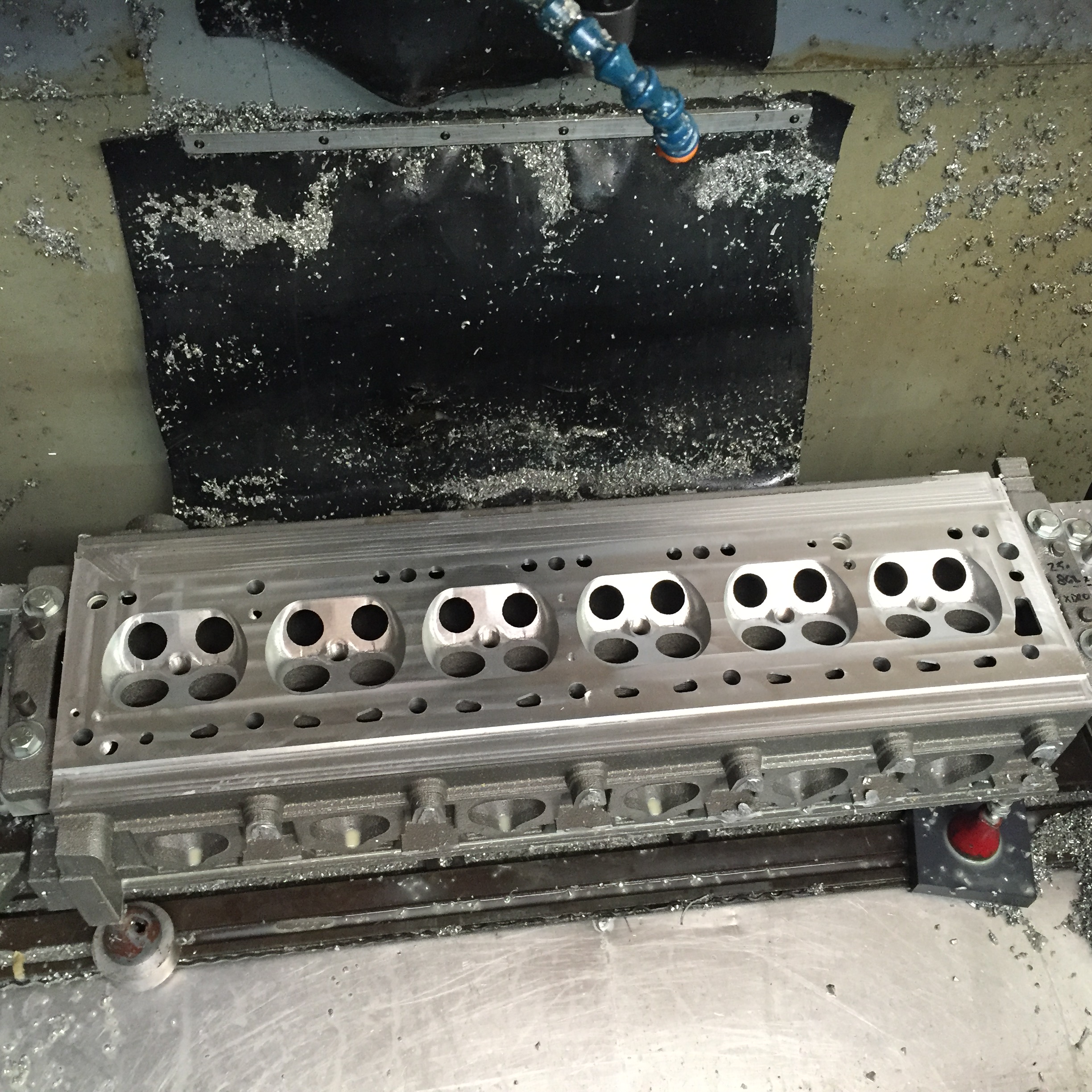
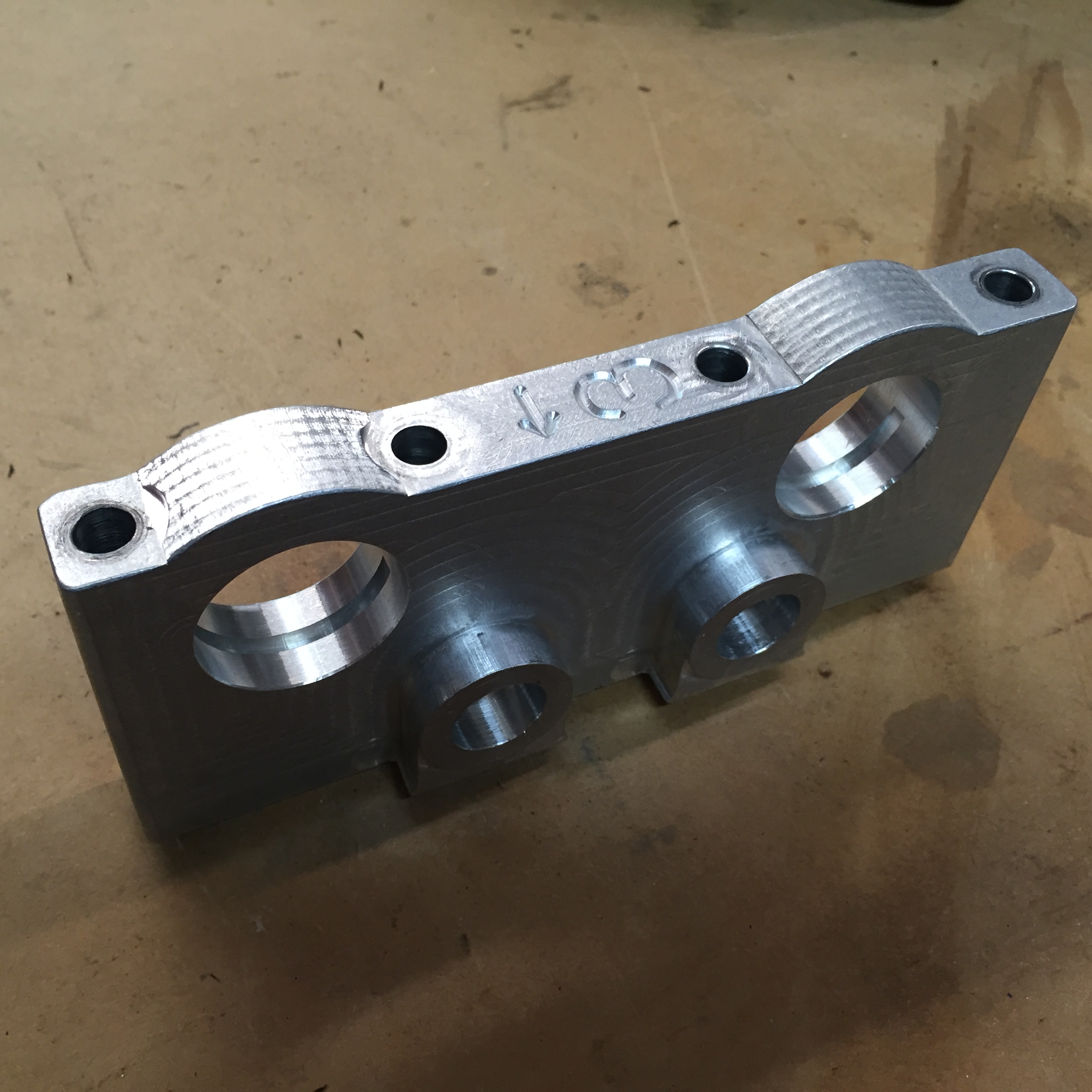
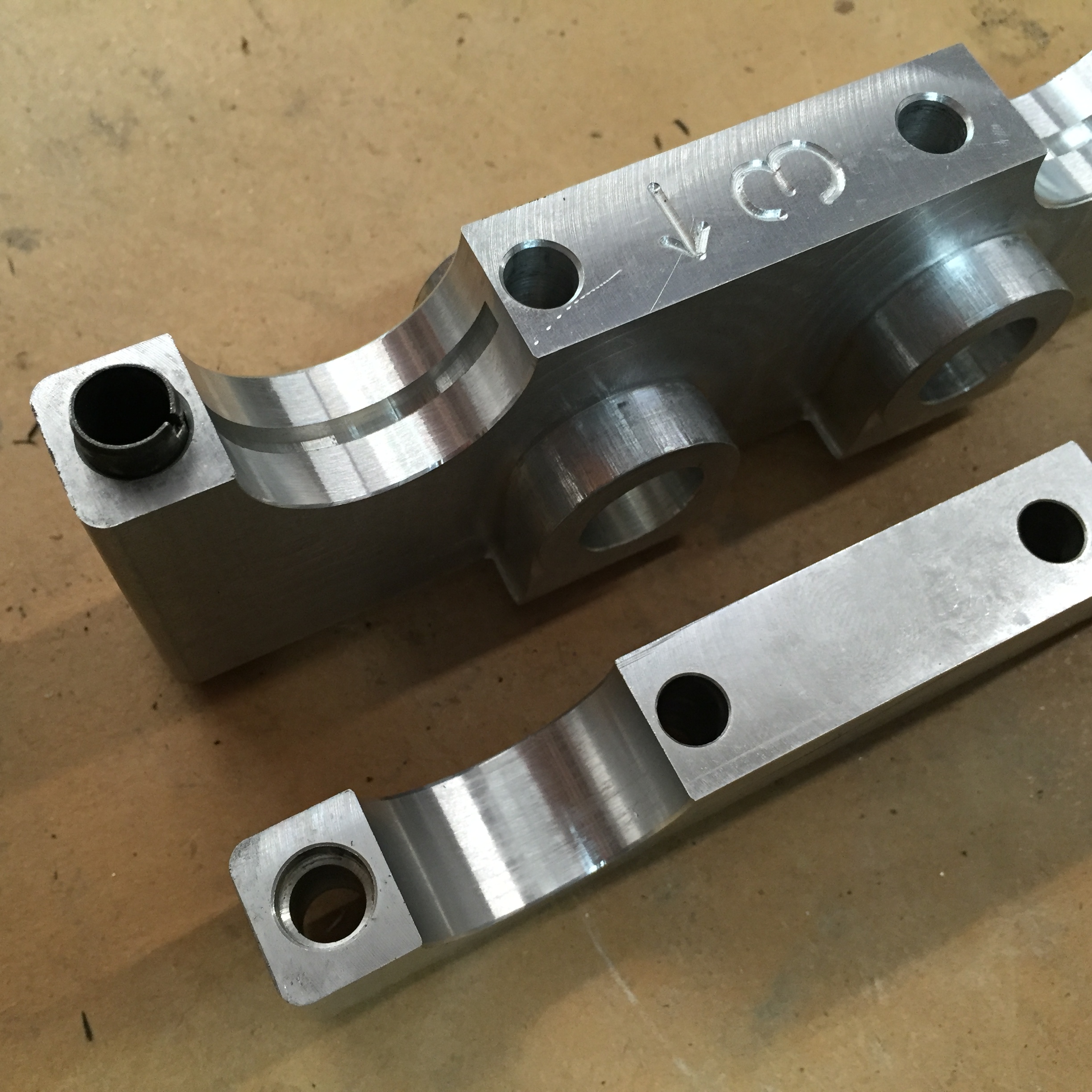
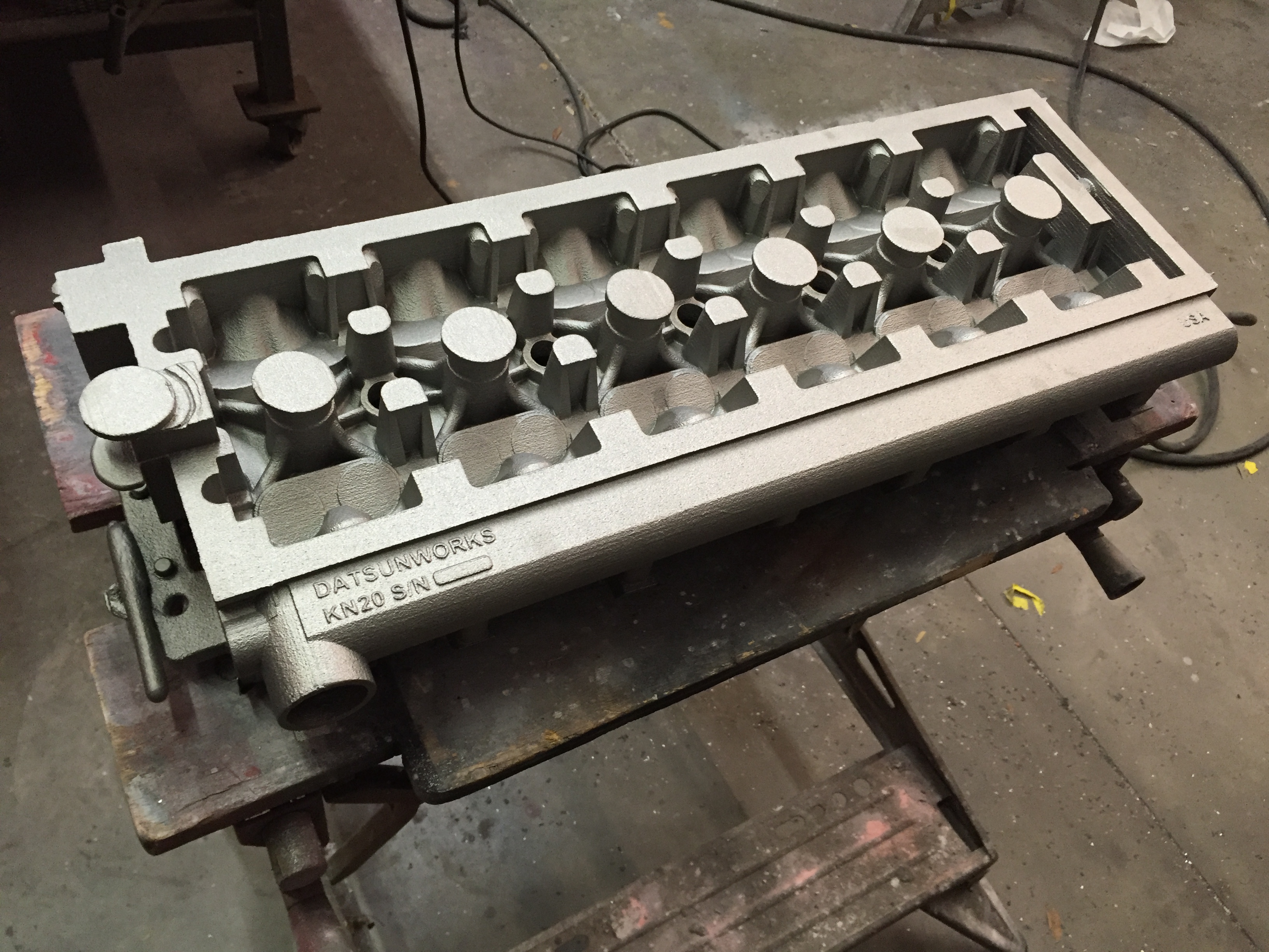
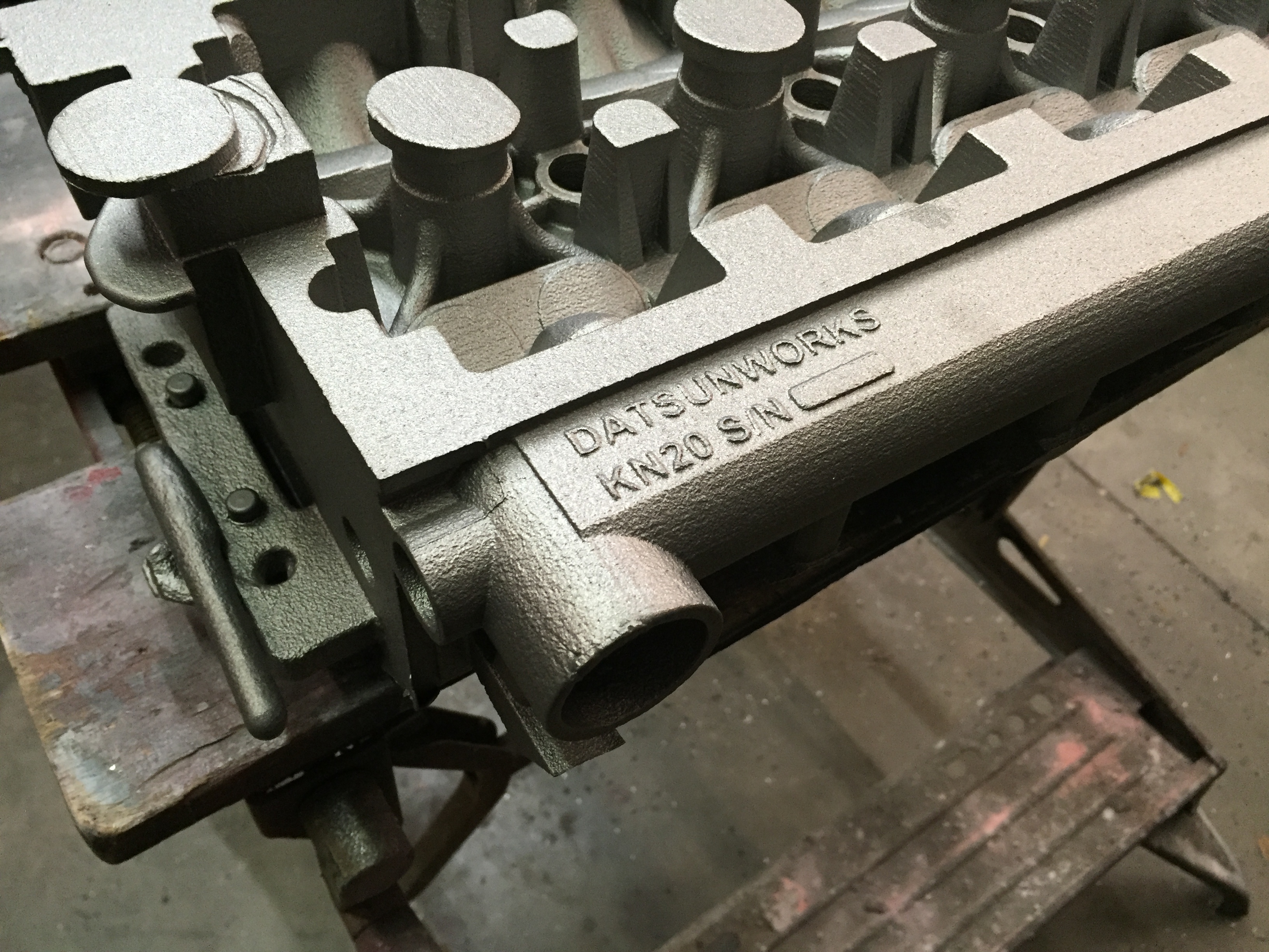
Here is a great shot that shows 3 of the upgrades. The sump, the feeder boss and one of the water exit ports.


IMG_1060


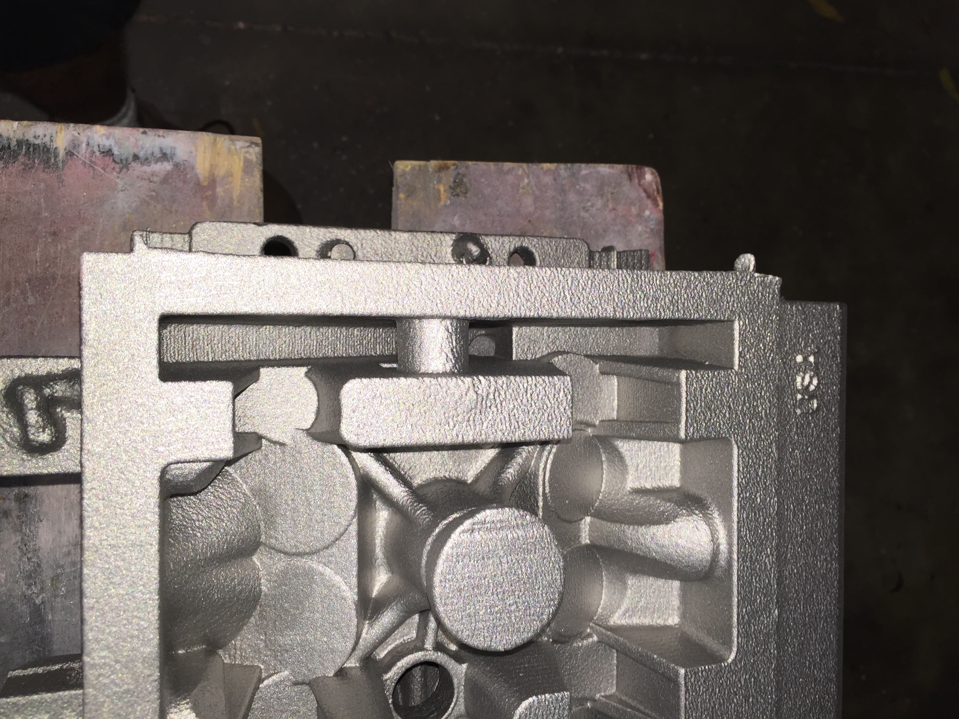
Here is the combustion area. The sand is really rough because I went a little overboard blowing out the loose sand. It all get’s machined anyway.


IMG_1058


Water outlet and core print in the front of the tube. The core prints are designed to be tapped 3/4″ NPT so that one could be uses for a sensor.

IMG_1057


Now I just need to find time for the machine work


Thanks

Derek


And it runs:)

The valvetrain noise is not as loud as it is in the video. I have about 30 min. of run time on it. Pulled the valve cover a few times checking things with no surprises. The revs in the video are up to around 5000.

Now comes the long process of getting everything dialed in. There are a lot of loose ends.

I’ll probably start sleeping better:)

Motor is in the car!

Got it installed without any major issues. Hood clears without any problem. Getting the valve cover on and off is tricky as the hood latch bracket is close. I think I can make it a lot better in the next version.

Prior to the install I did the final lubrication test with the cams in. The pressure came up about 5 psi and I saw oil seeping around every cam bearing journal. Still lots to do but this is a major milestone for sure.

I know the wiring is a mess and it’s something I need to address.

IMG_0947


Before I installed it I took a few shots of it assembled.

DSC_0046

DSC_0054


I made up custom wire looms out of Type 1 PVC

DSC_0055

Made some progress on the cam gear adapters.

Each one is a 2 piece affair. The inner hub is keyed to the cam and the outer hub holds the gear. The back side of the inner hub holds a thrust bearing. This way I can shim the bearing if I want to decrease the clearance. There will be 5) 5mm bolts in the outer flange to lock the 2 hubs together.

IMG_0920

Assembled hub.

IMG_0921

With gear. I had to turn the gear around to get it to line up with the idler gear.

IMG_0922

And the best part is it fits!

IMG_0917

Up next is the slots and the bolt holes. I’m going to see if I can get the cams close degree wise before I key the hubs. This way I’ll be able to utilize the full travel of the slots.


I’m already working on simpler solutions for the next ones.

Camshafts have arrived!

Finally have the cams. They look great and all the dimensions are right on the money.

IMG_0914

IMG_0915

I stripped the rockers from the towers and mounted the cams up in the head. It was snug but I could turn them. Not by hand but with a wrench on the flats it moved very easily. This was a big concern of mine from the beginning but I think it’s going to be ok. Now I can start on the cam gear adapters.

Spark Plug Wires

Got the plug wires from Magnecore. Great work as usual. I’m not crazy about the look of the boots but trying to come up with something I liked started turning into another rabbit hole. The boots are from a Honda K24.

IMG_0911

Made some custom looms out of grey type 1 pvc.

IMG_0910

IMG_0912

The EDIS coil mounts up under the front intake manifold so for the most part it should be hidden.