First Casting

This is by far the most complicated casting I’ve ever designed. And was really surprised that it poured on the first try.

SDC11054

SDC11050

SDC11051

Here is the 3D printed water core, ports and combustion chamber.

IMG_0231

These are the 3D printed parts all assembled and being incorporated into the surrounding mold. I design this way to save a ton of money.

IMG_0252

After the pour.

IMG_0257

If you want an idea of how detailed 3D printing sand can be check out this lettering.

IMG_0280

More Design Work

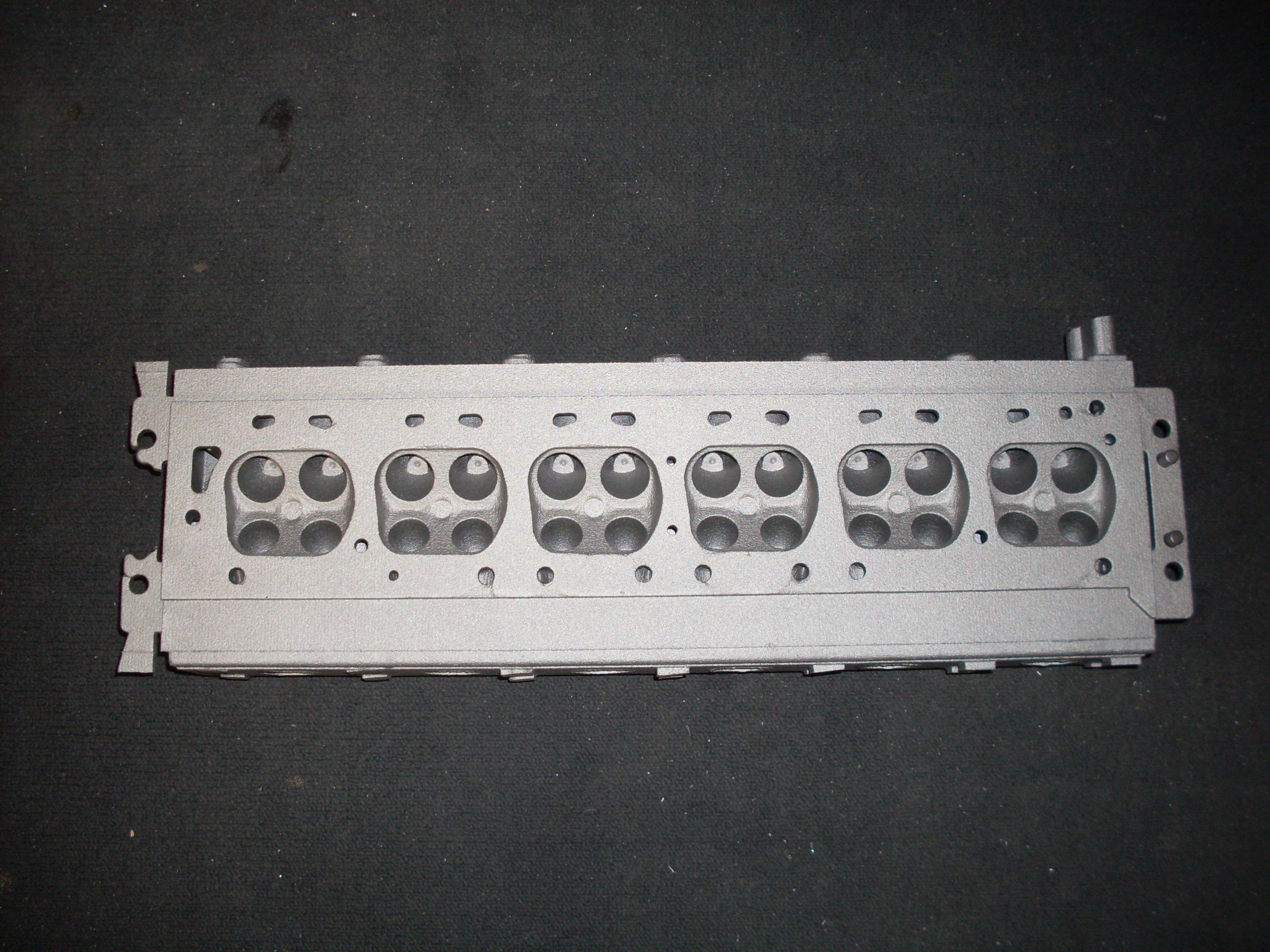
Now I could finish modeling the front and back of the head.

timing gears

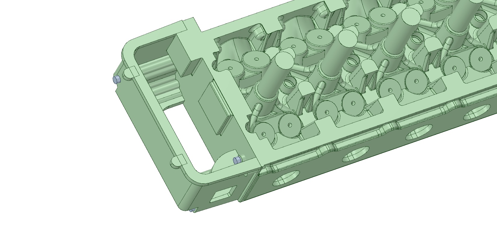
Next the front timing cover. The water outlet exits the head in the front and makes a 90 degree turn through the timing cover where the thermostat housing will mount. This design has been one away with as it was deemed that it wouldn’t provide enough flow for turbo cars. It was too late for this head though.

timing cover

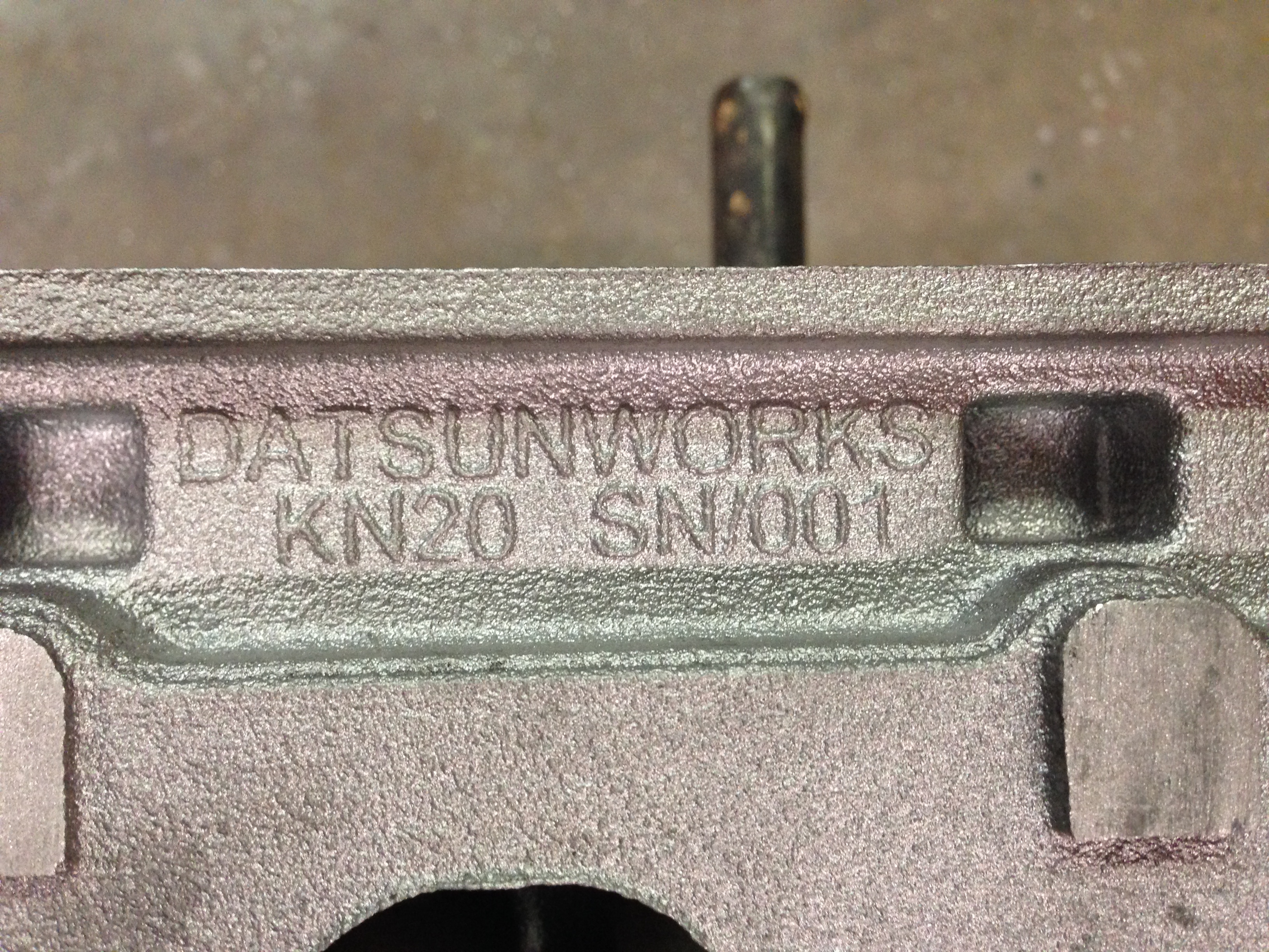
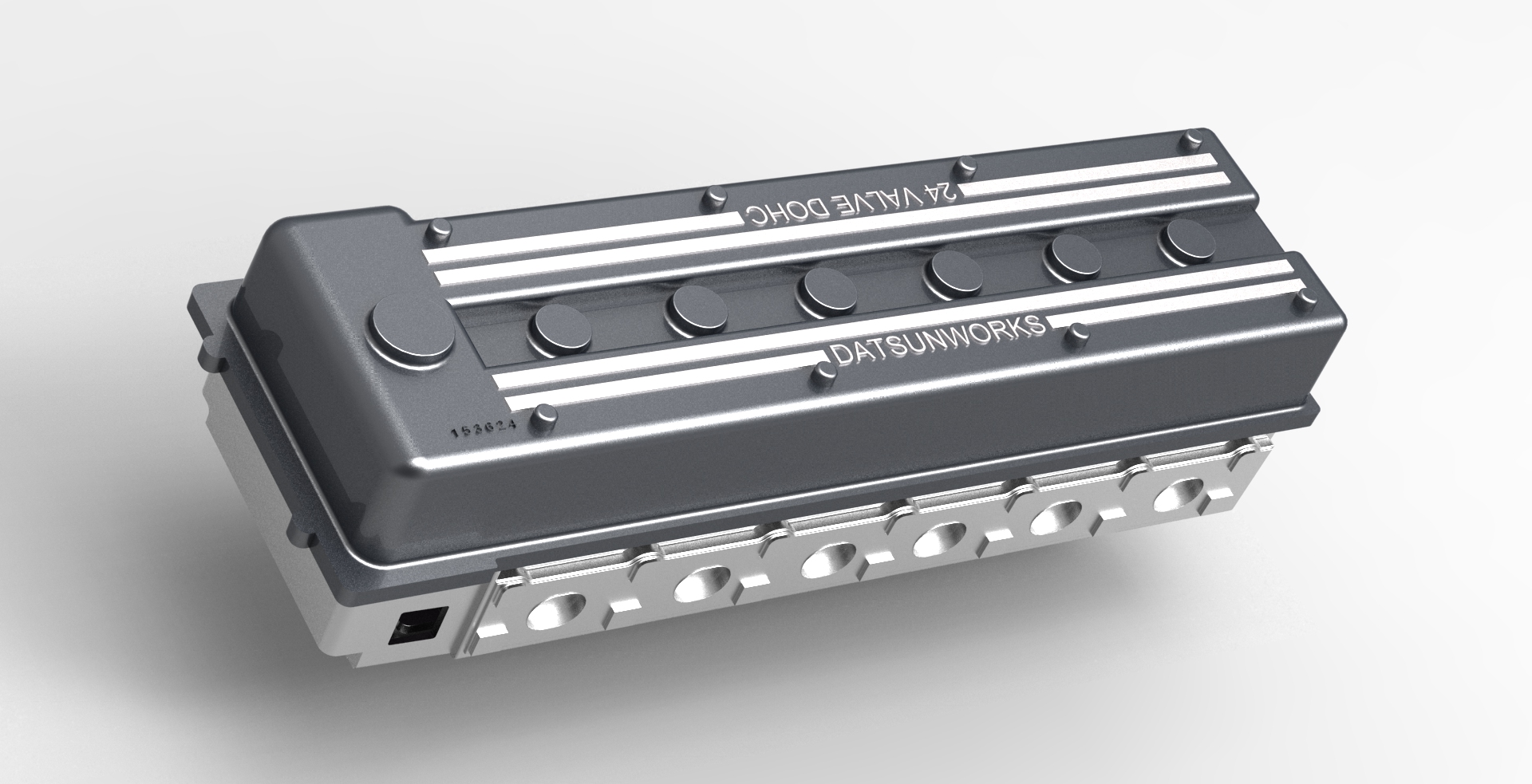
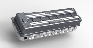
Now the valve cover. The K20 cam towers kind of dictated the overall size but I was still able to get the styling I was looking for. I was originally going to machine in the lettering but I put it to a vote and this design won out.

VC with head

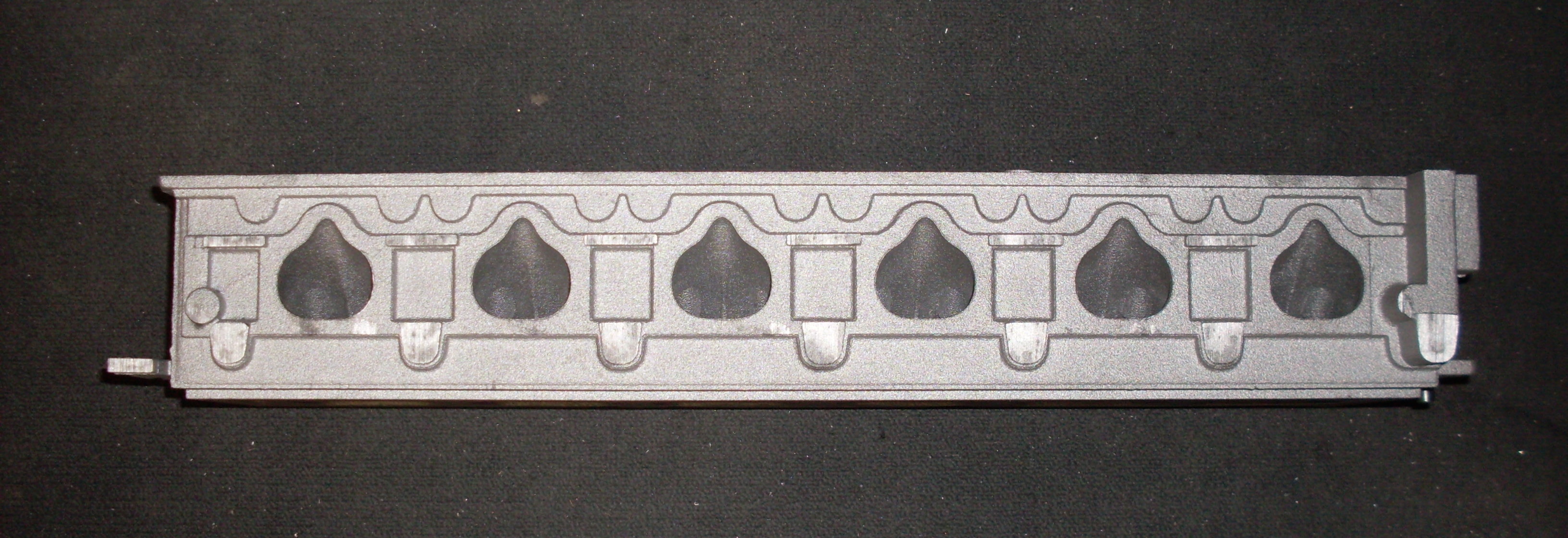
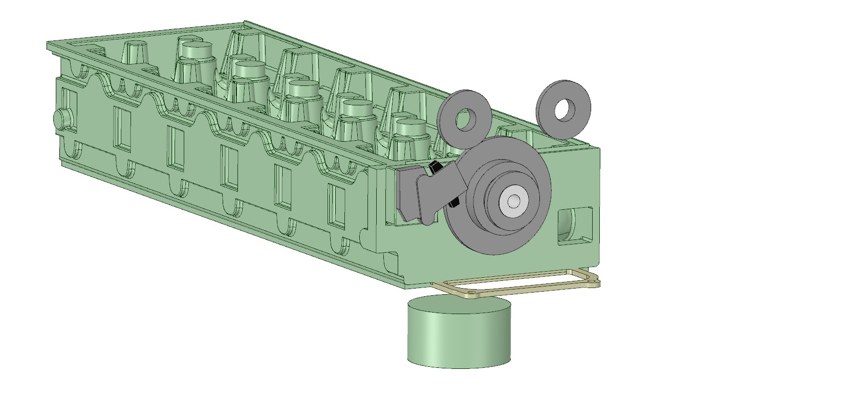
After talking with Jeff about his testing on coolant flow I decided to get the most out of the 3D sand printing process as I could. I designed a water jacket that would be pretty hard to duplicate traditionally. There is a lot of surface area so hopefully there will be large improvements in cooling.

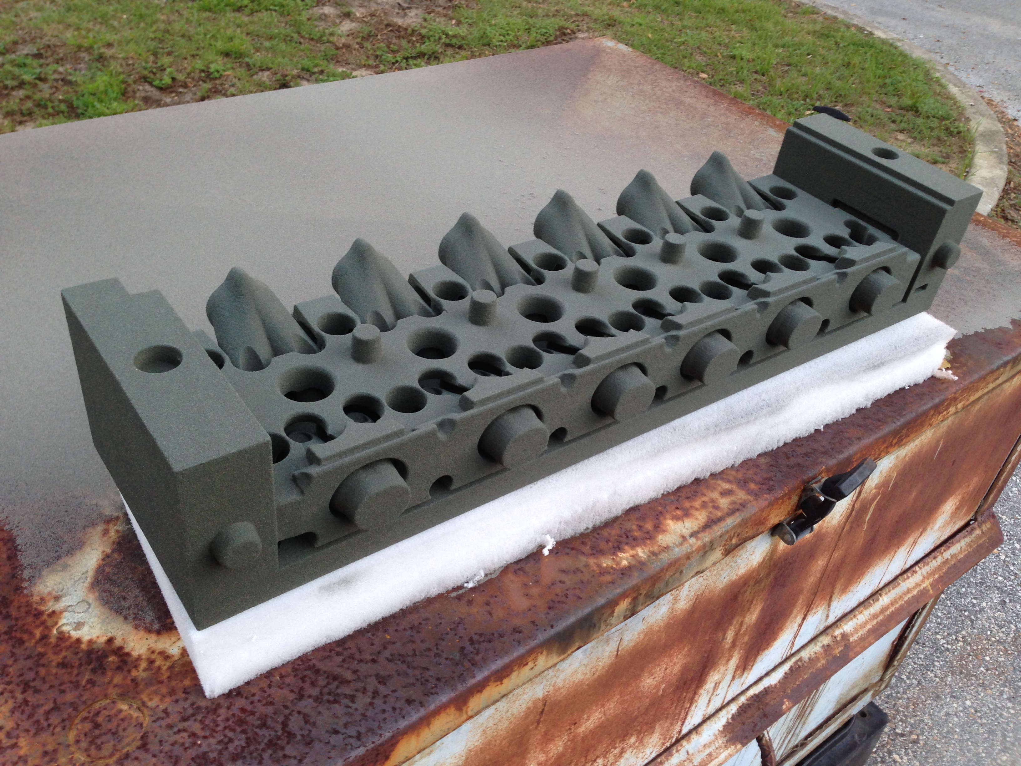
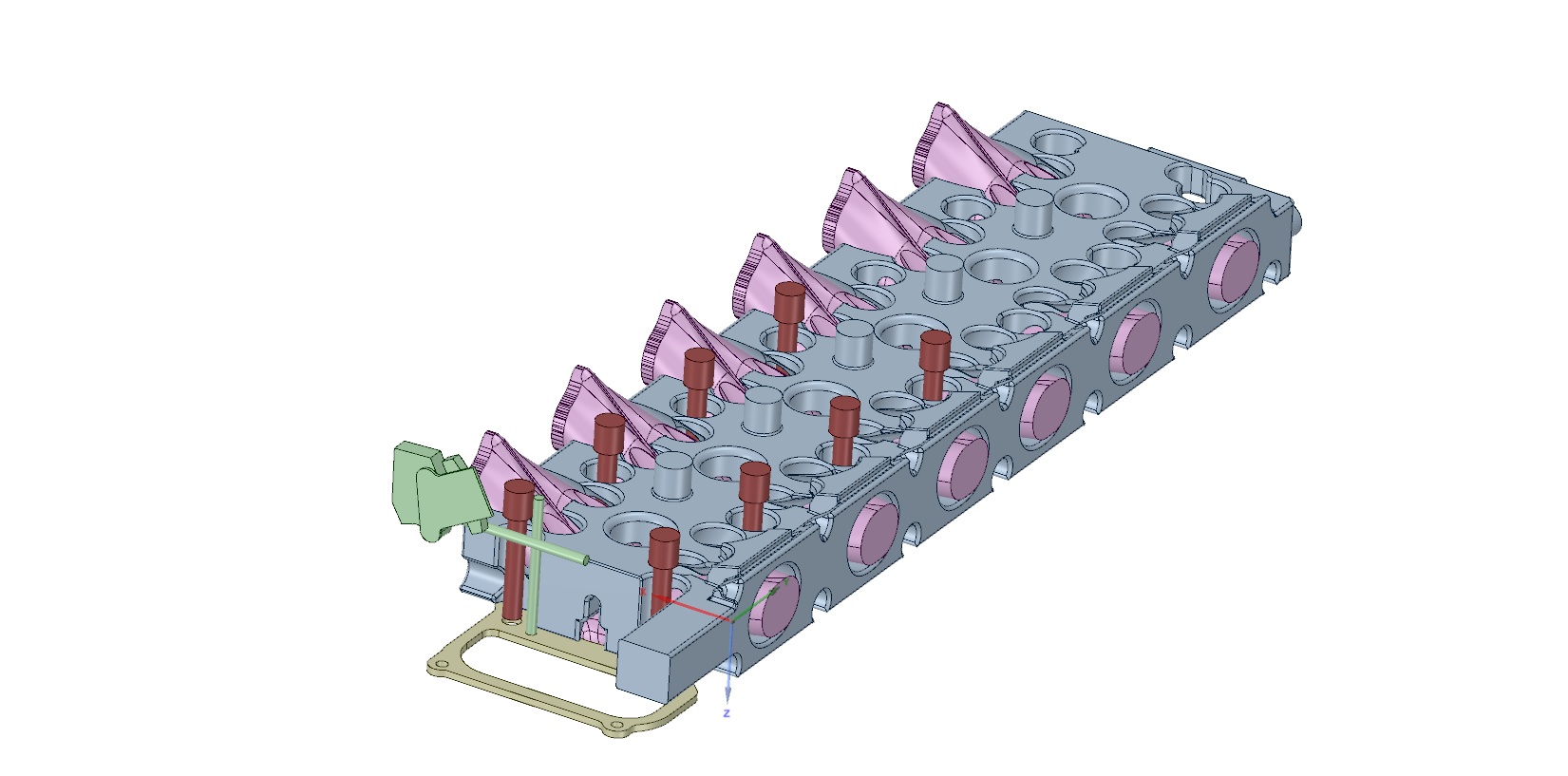
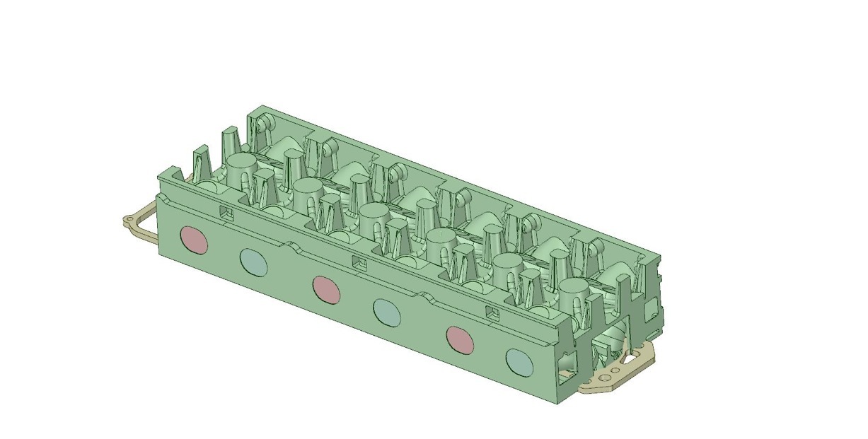
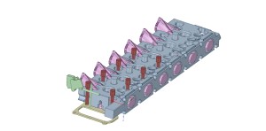
Here is a nice shot of the intake and exhaust cores, water core, and upper tensioner. You can see where the cross drilling will go to supply oil to the head, tensioner and idler gear lube.

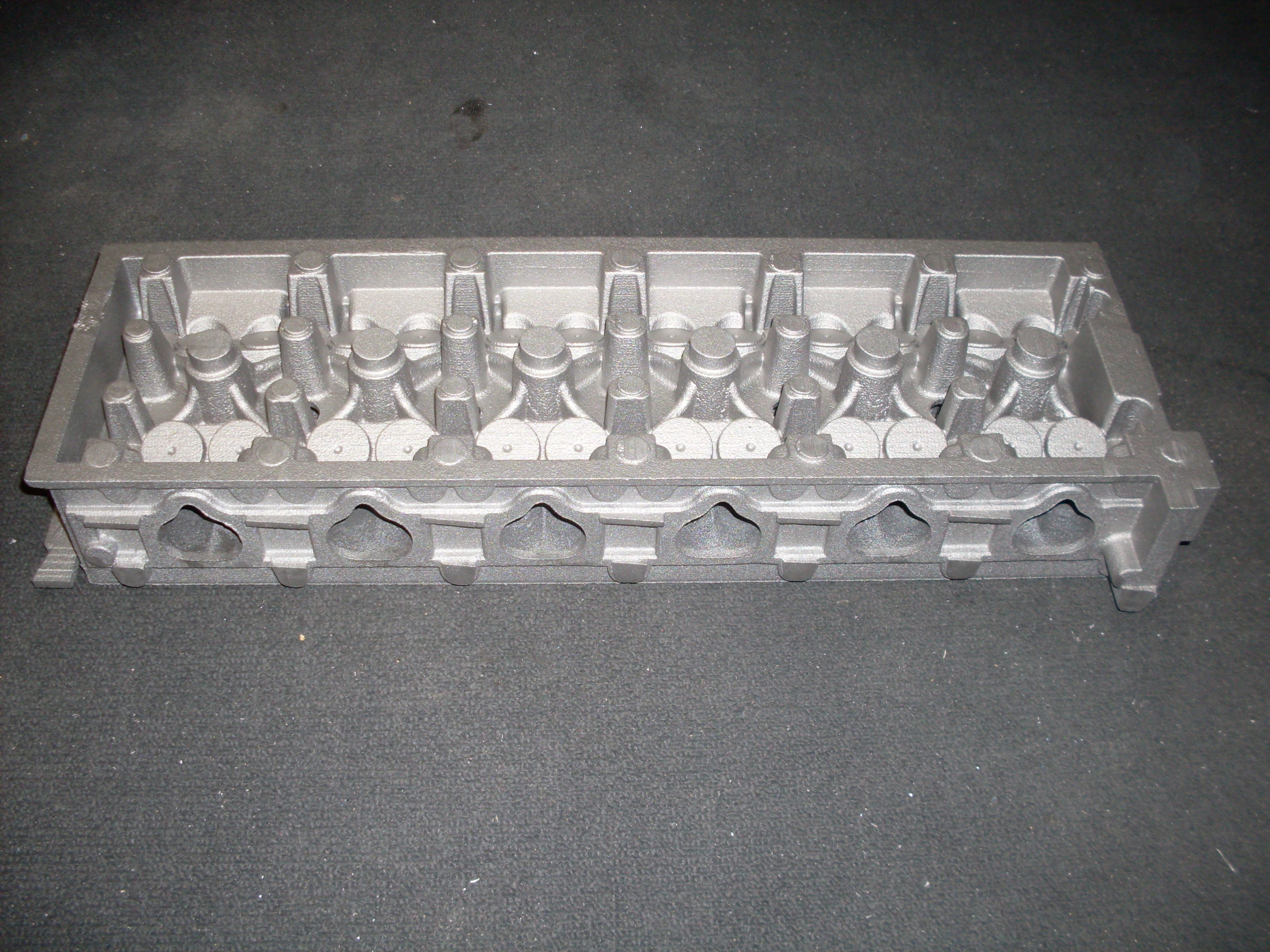
There will have to be additional oil supplied to the last three cam towers as the single feed in the front won’t cut it.

front combined

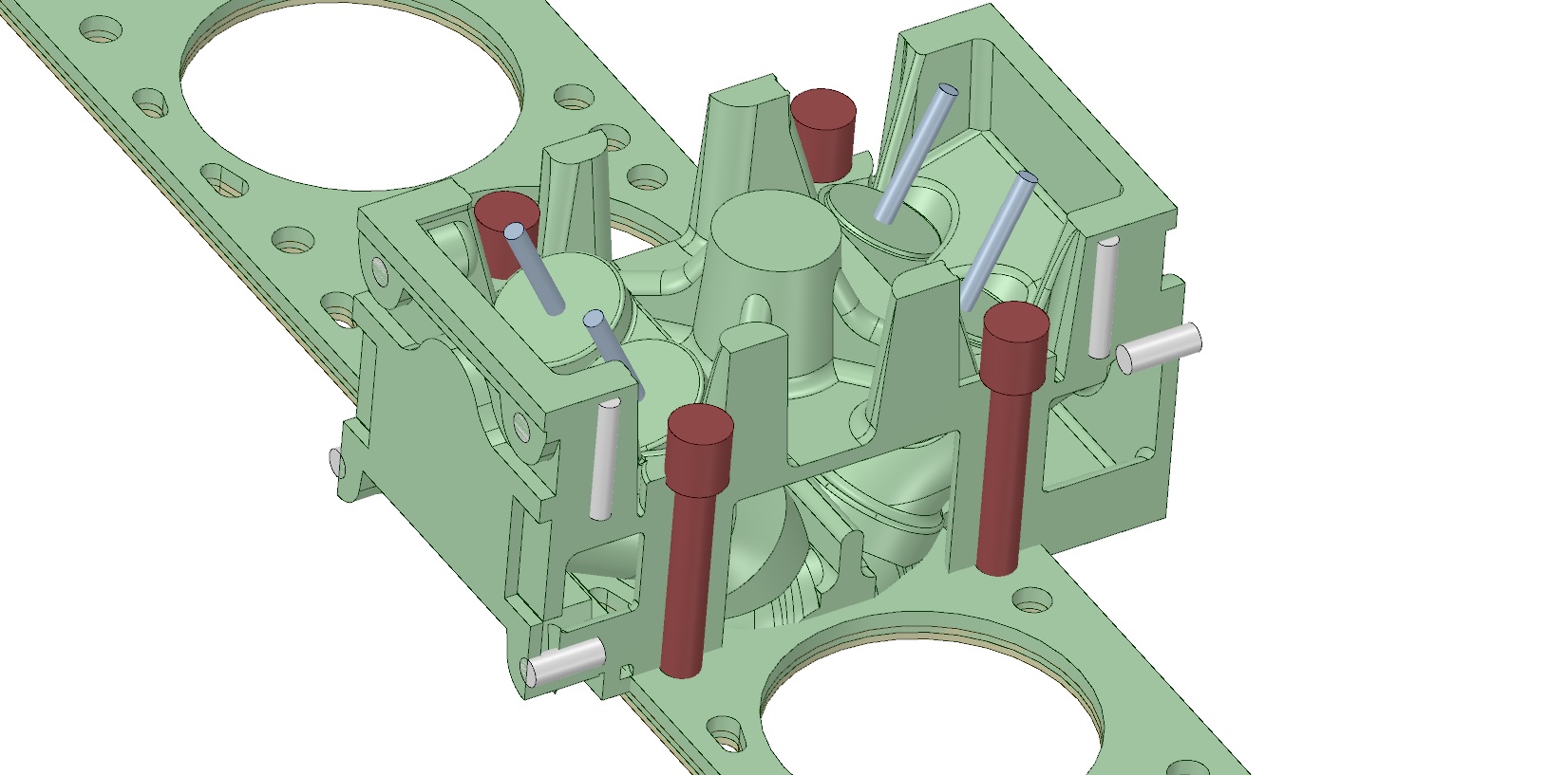
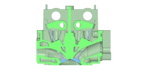
Here is a cross section of the head. The cut plane is through the center of one of the intake valves so the ports look a bit off. There is machine allowance on the bottom so the combustion chamber is a little larger than it will be after surfacing.

rocker cross section

The design work on the head is pretty much done at this point so it’s time for mold design.

Timing Chain

Jeff and I had a long conversation about pros an cons of various designs. The preference would be a single chain so I ordered up a K20 set to see if it was workable. NOPE.

Lower timing gear is too small to bore out to fit the L6 crank snout Back to the drawing board.

I decided to give the KA set a try. I decided the Altima set would be a good choice as it’s only a single row chain up top. With the roller rockers I don’t think you need a double row. But there is nothing stopping people from using a double row if they feel like it.

I did a rough mockup on a piece of wood mounting all the pieces. I used my router to plot out the locations of the parts and drill the mounting holes. This gave me a point of reference.

IMG_0748

Then I machined a chunk of plastic so I could actually mount it to the block.

You can see I’m trying to incorporate the KA guides and lower tensioner but that won’t happen without a new lower timing cover.

Image 1

Here is the lower section with stock modified L6  components. The only tricky bit is I need to remove one link from the chain. I think this is a workable solution.

Image 2

Initial design and scanning.

I get a PM from TonyD in September of 2012 about the Goerz-Paeco DOHC L6 Head coming up for air.

Which led to a brief discussion about what would be involved in producing a head. And that was the end of it… Or so you thought.

Tony and I started trading emails about the feasibility  of producing it and what kind of heads we could use as a donor for the valve train. Tony suggested bringing Jeff P on board because of his work with cooling the L6 head. Tony and I kicked around RB and KA motors for a while and then Tony suggested checking out theHonda K20. Bingo. Removable cam towers, factory roller rockers and a plethora of aftermarket parts. I called one oh my clients that is big in the import drag market and  procured an old K20 head. I did some quick measurements and decided that it was probably workable. And so the journey began.

The idea is to use the cam towers and valve train from a K20.

I grabbed a quick scan with my white light scanner of the exterior. It’s dirty because I’m only using it as a reference scan to design against.

top

I imported the scan into my solids program and then proceed to replace the mesh with solids.

exterior 1

Jeff provided me with a great CAD drawing of his head gasket to work from. I decided to take a module approach to model the head. I made a single cylinder complete and the copied and offset it for the other cylinders.

single module final

I then pulled the solids together to create a single model

Image 3

I was pretty much at a standstill until I could figure out the timing chain setup.

Welcome to my custom twin cam cylinder head build for the Datsun L6 engine

Although I have a build thread on HybridZ I thought it would be a good idea to create a blog for this project.

First a little about me. I’ve been involved with 240Z’s in one way or another for over 30 years. It pained me to type that:) I’m an independent pattern maker for the foundry industry. I have a fairly high tech pattern shop. Two CNC routers, Two CNC mills, 3D white light scanner and all of the traditional saws sanders etcetera that you would normally find in a pattern shop. I also do short run vacuum forming and CNC machine prototype and production work on castings.

Back in 2007 I decided I wanted something unique for my 240. Being a patten maker it had to be a casting. Doing research led me to HybridZ. Here are 3 links to the build. It’s an interesting read if you want to know what goes into a traditional sand cast intake manifold. I received an enormous amount of help and encouragement from the HybridZ community along they way.

Design stage        Pattern making       Casting and machining

The intake manifold project was great but what I really wanted to do was a twin cam head. At the time it was just too much of an undertaking to do with traditional pattern making tech. Even with CNC machines. It rattled around in my head for a while and as they say timing is everything. I was starting to use a fairly new technology that produces foundry sand molds via 3D printing. The results were amazing. Not only were they patternless the normal constraints of split boxes and draft no longer applied. The more I worked with it the more I WANTED to work with it.

And then I get an email from the infamous TonyD