Well disaster has struck

Drove the car Saturday nite to pick up a pizza. Ran great. beat it as usual. Parked it overnight. Got up the next morning and fired it up ran a little rough for a couple of seconds then it ran a lot rough.  Towed it to the shop, pulled the plugs and number 6 shot a geyser of coolant.

The #12 intake seat dropped out and the result was a wiped out chamber and piston.  Bits of the seat smashed the quench area enough to deform and crack the head.

I’m about 99 percent sure it was improper installation at this point. The seat bore is not cracked and I never overheated the motor.

I was going to change it out at some point with a production head anyway but realistically with the current demand I have for heads it will be 6 months or more before I’ll be able to make it happen. I could repair it but since the motor is toast as well I’m better off concentrating on getting the heads into production.


Parts are in the house

Got the head back from the foundry and for the first time I have all the parts under one roof. Figured I’d take a family photo:)

Guess I better get busy on the milling machine!

Long overdue update

I’ve been shirking my duties on keeping the blog updated so this has quite a bit of info.

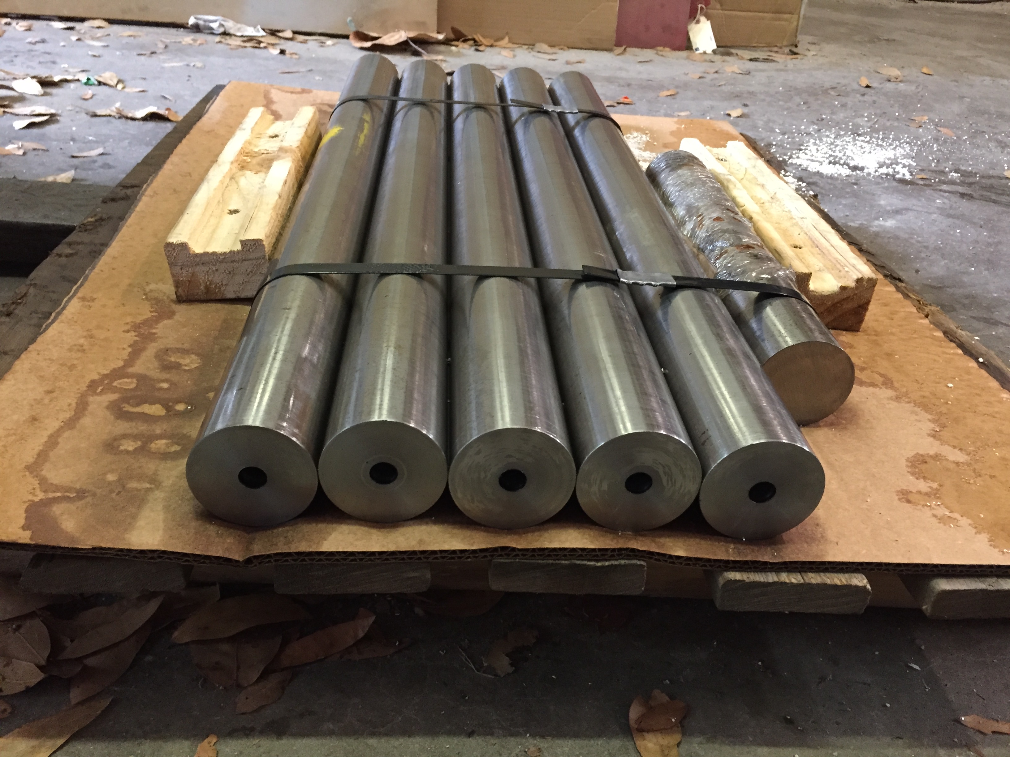
I cast a third head and it came out great.

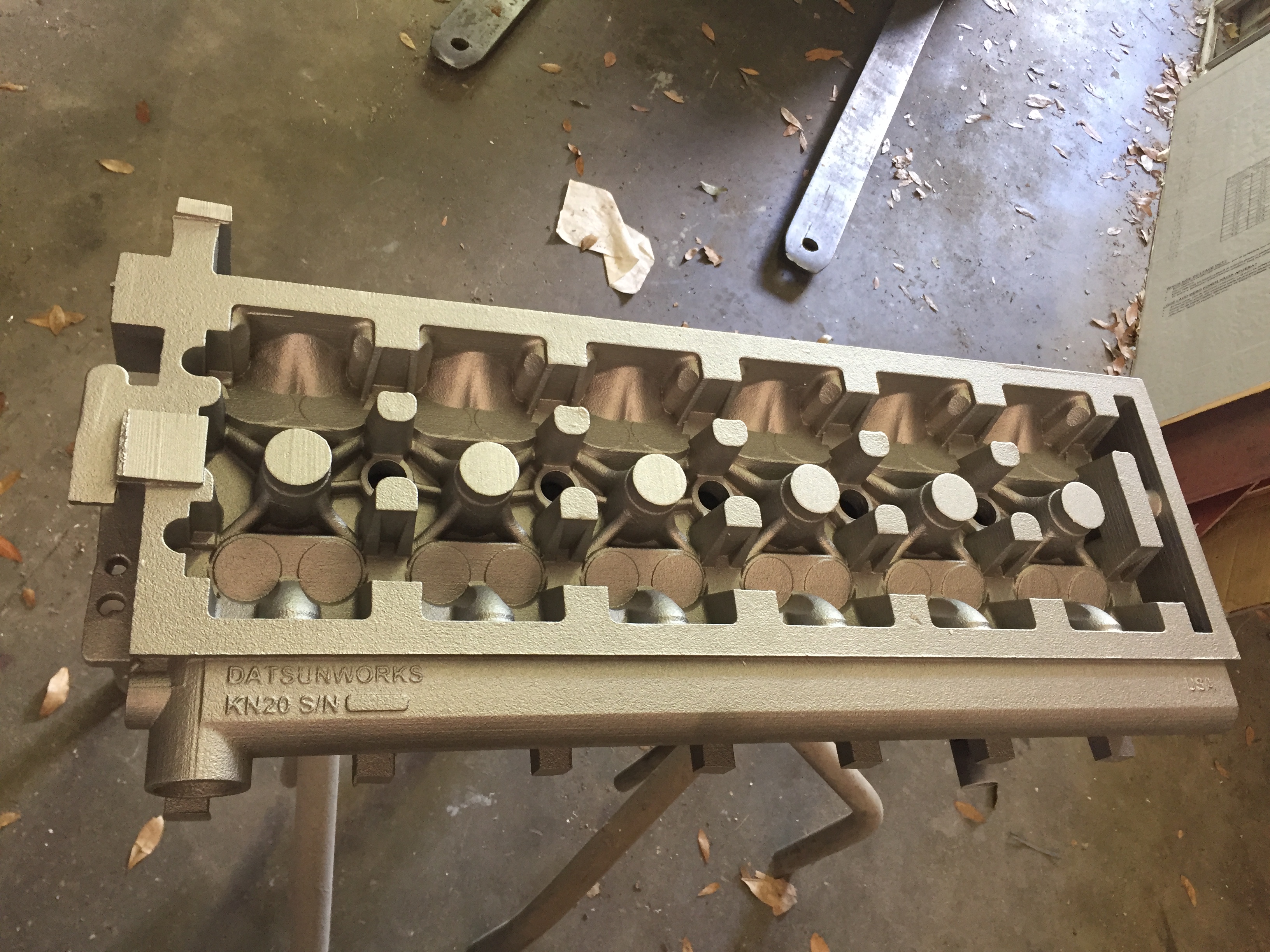
This one is heading out to Rebello Racing for one of his customers.


So a whole lot has been going on behind the scenes as far as the processing of the raw castings and some big design changes. First the processing. I’m always reading about casting and cylinder heads. I was researching different methods of controlling casting shrinkage and porosity and stumbled across an article on how Edlebrock casts their racing heads. Not their production heads. They mentioned that they offer an optional service called “Hot Isostatic Pressing” Or HIP. The HIP process consists of heating the casting to a set temperature in a pressure vessel and then pressurizing it to as much as 30,000 PSI. This basically compresses all of the porosity  out of the metal. One comment from the article that stood out was it makes the casting almost as dense as billet. It’s so much denser that they had to adjust all of their machining speeds and feeds lower to accommodate the extra hardness. I’m now setup with a HIP provider and just had the last casting done. Because it’s a heat process the head needs to be heat treated afterwards. It’s currently at the foundry in the furnace as I type. I’m pretty excited about this since porosity is in every casting to some degree. You control it the best you can but there is always some.

Going forward I’ll most likely forget about X-raying the castings since if there is a large amount of porosity it will show up as a depression or a complete blow. I’m also hoping to do away with resin impregnation since there should be no leaks. I’ll know better on that after I finish machining and do the pressure test.

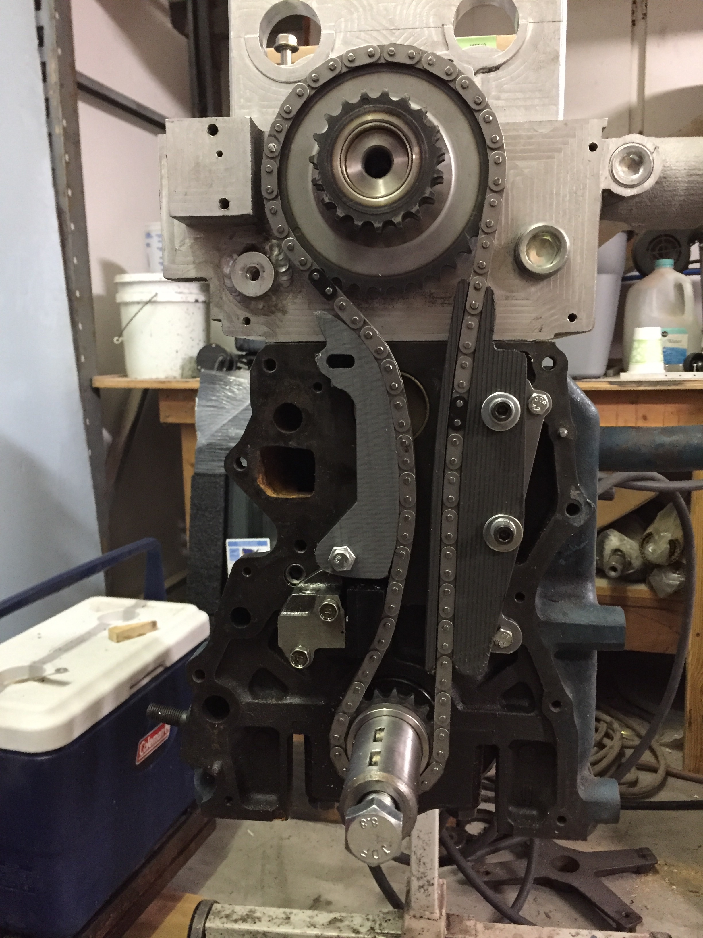
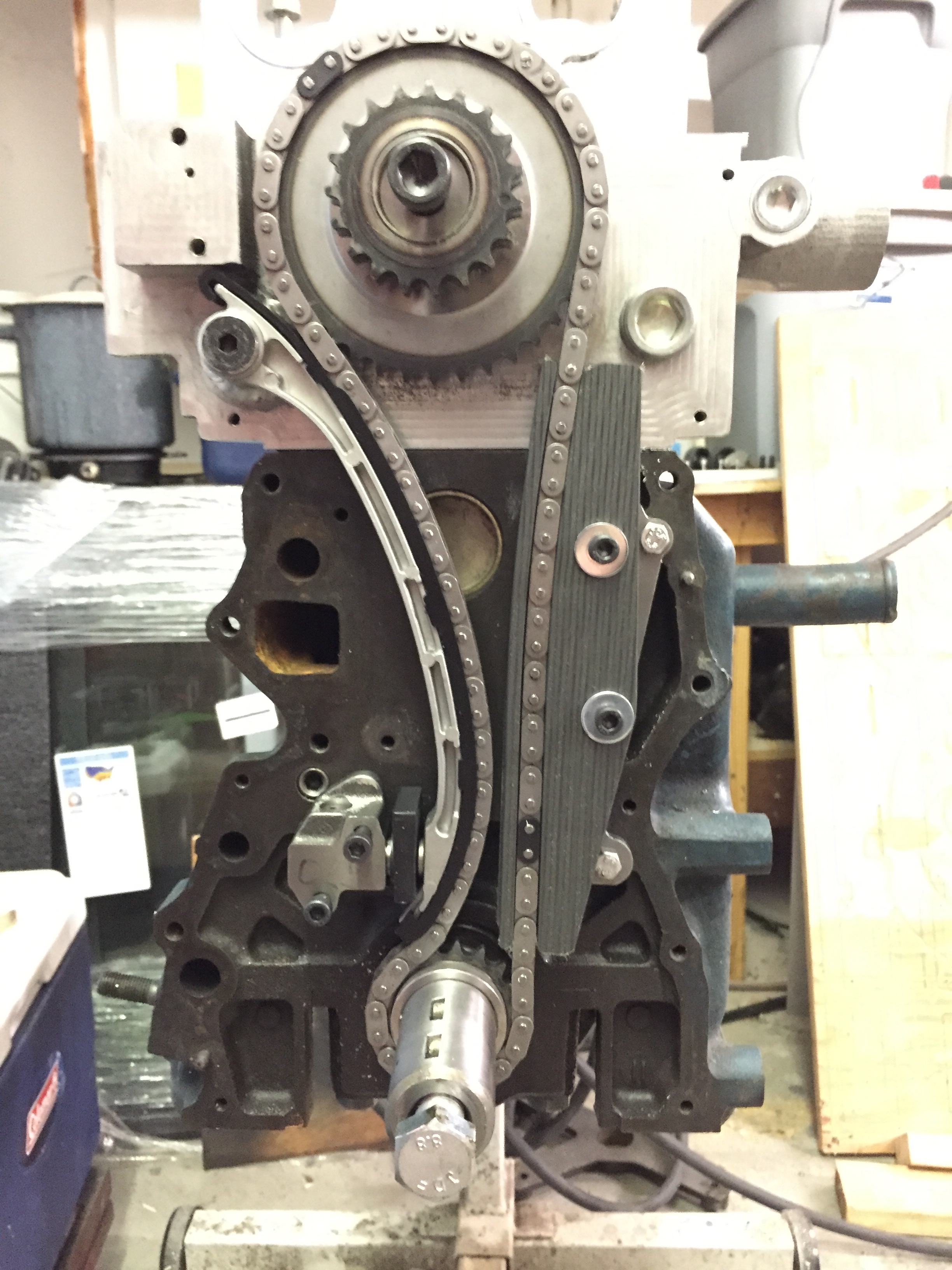
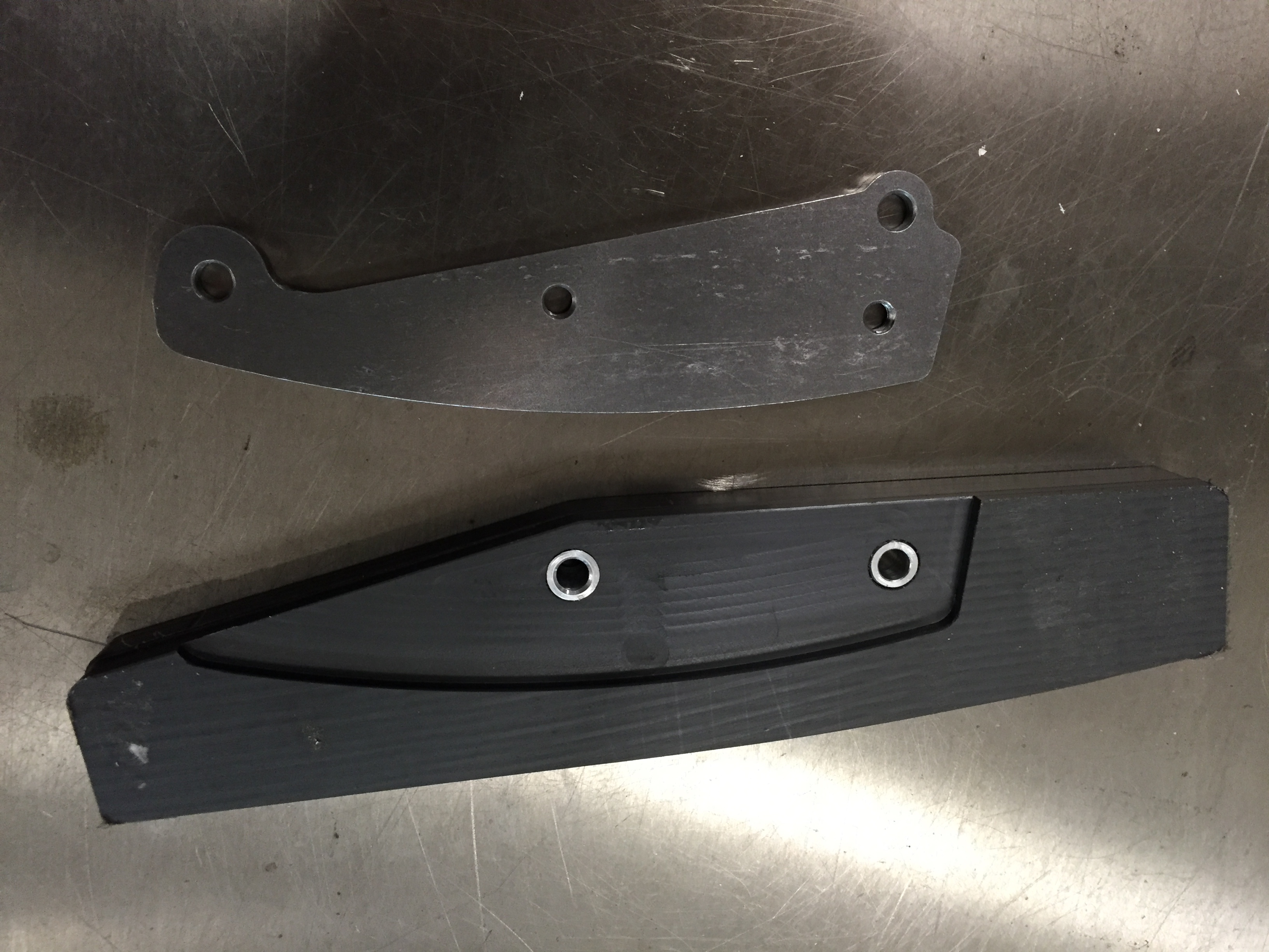
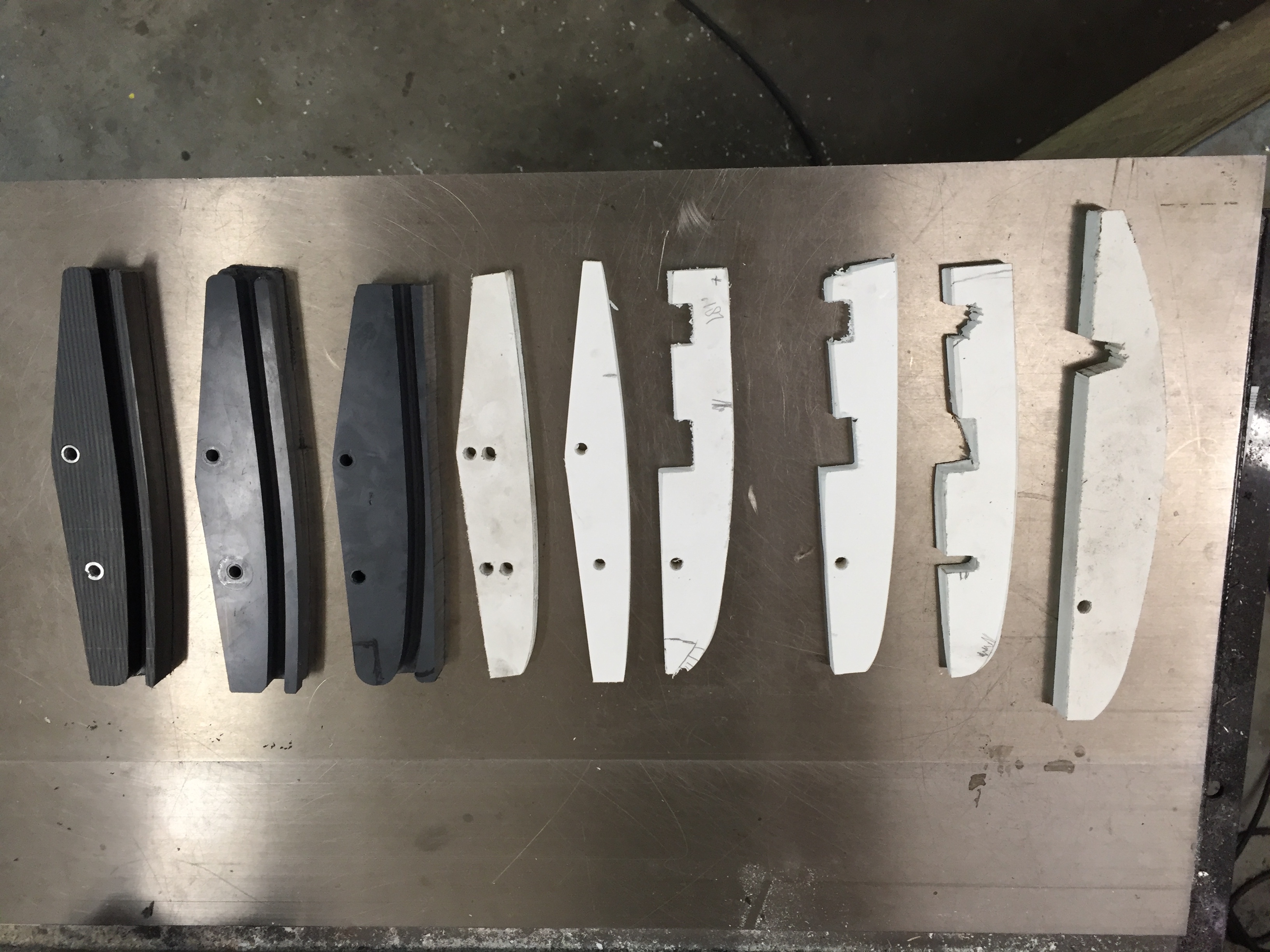
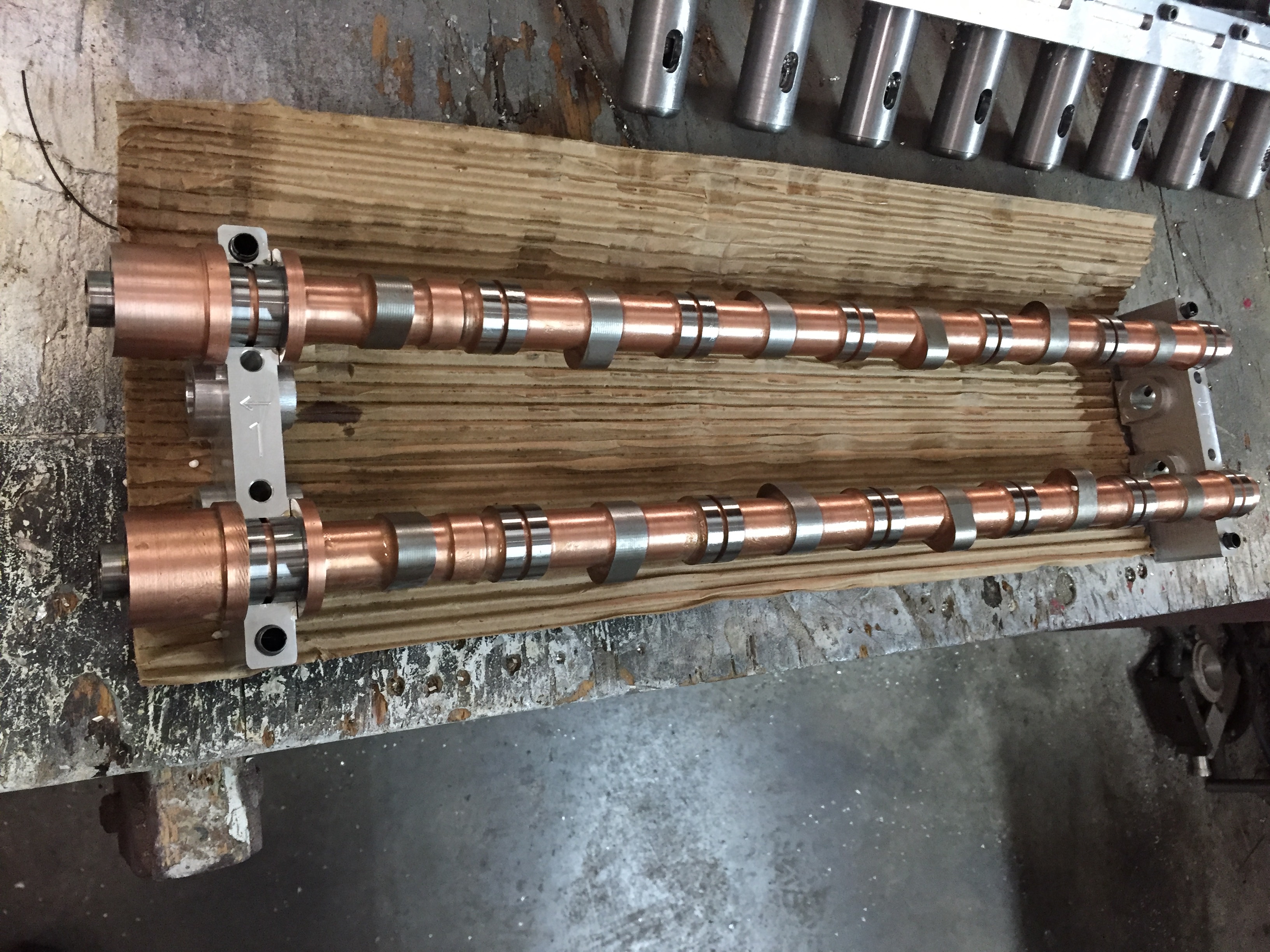
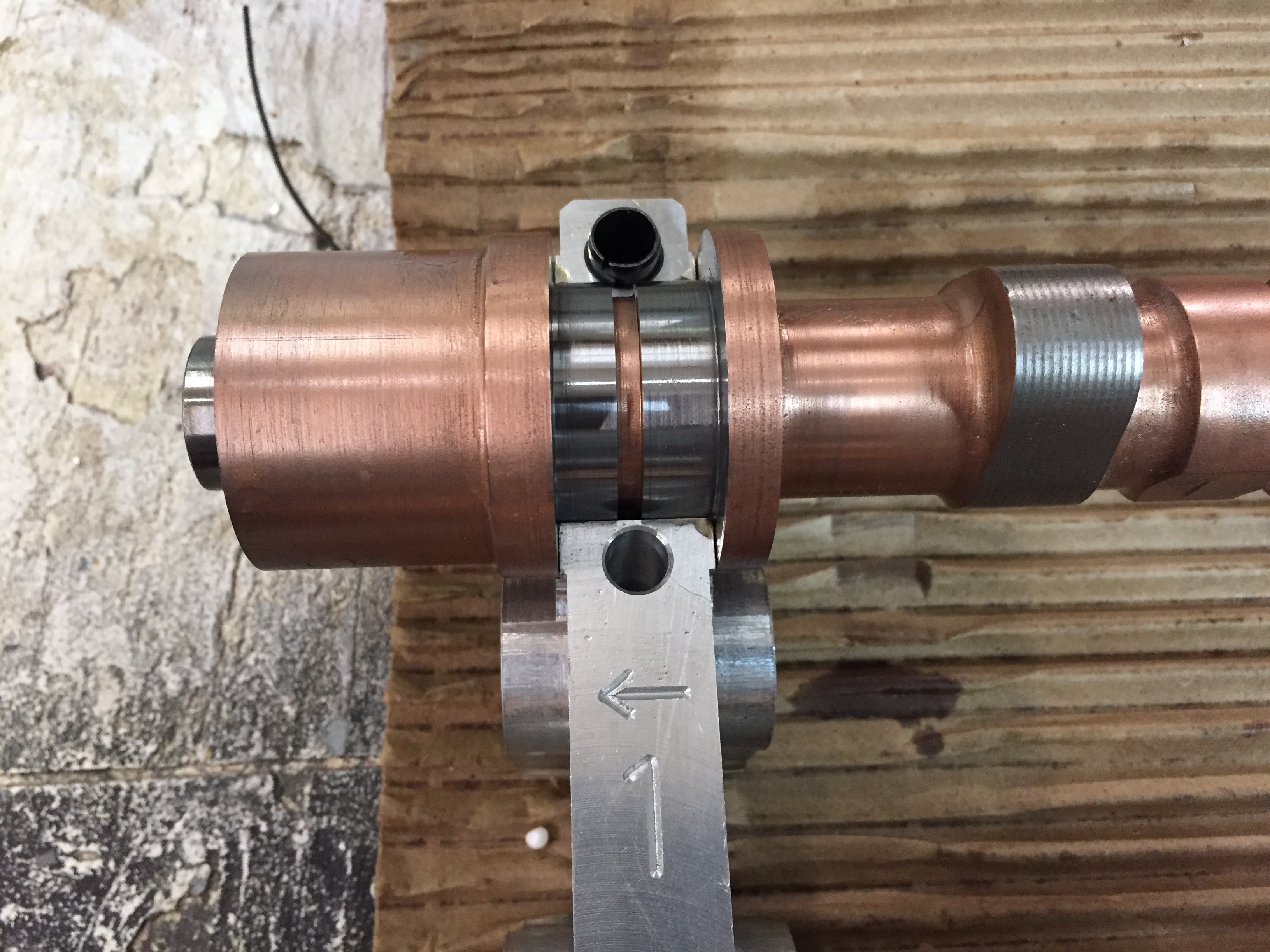
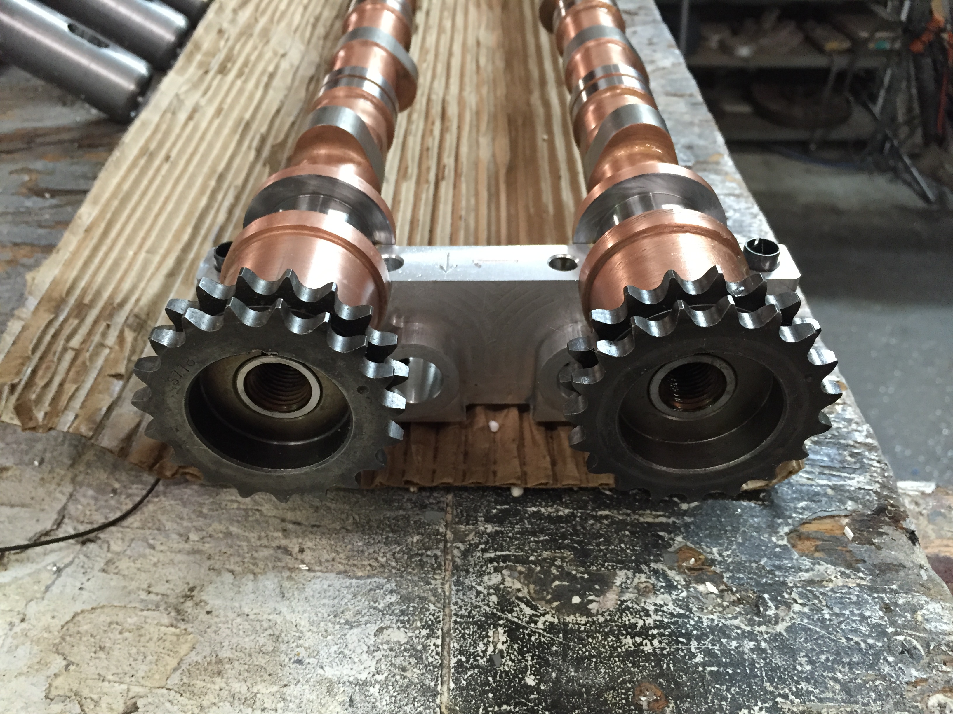
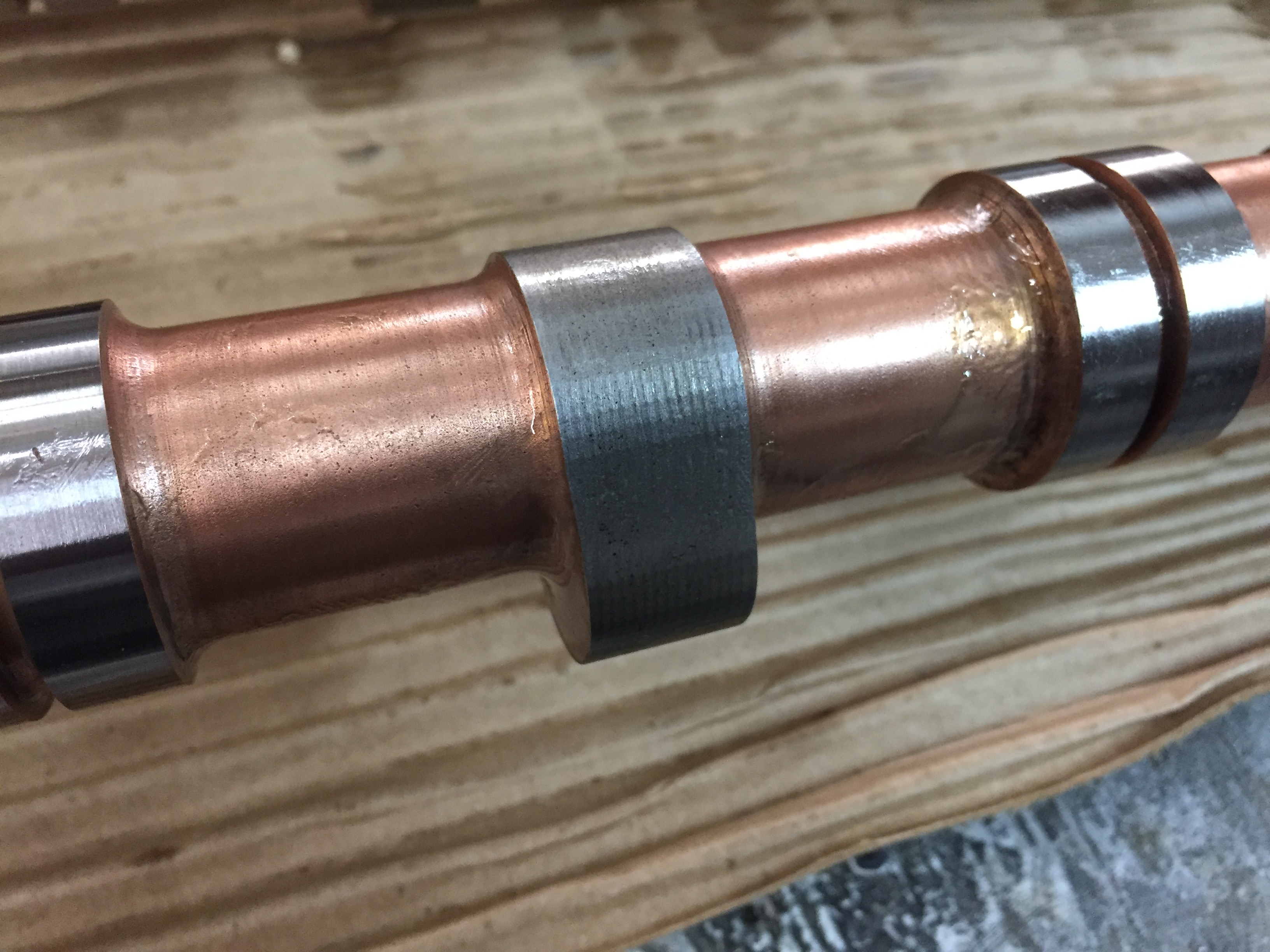
And now for the design changes. I have worked out how to implement Variable Cam Timing. This was no easy thing for sure but I’m all but certain it will work mechanically.  The basic idea is I’m sticking with the KA24 lower chain and Idler. But I’m modifying the idler to accept a Honda K20 steel exhaust cam gear. This will allow me to run a shortened Honda chain and gears from a K20. Here is a picture of how that looks.


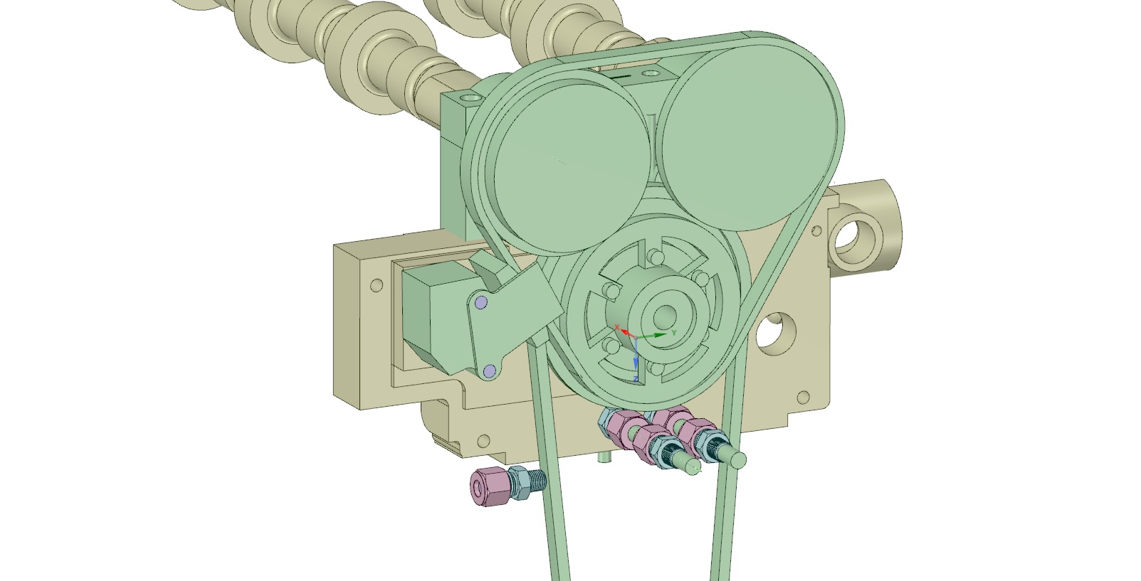
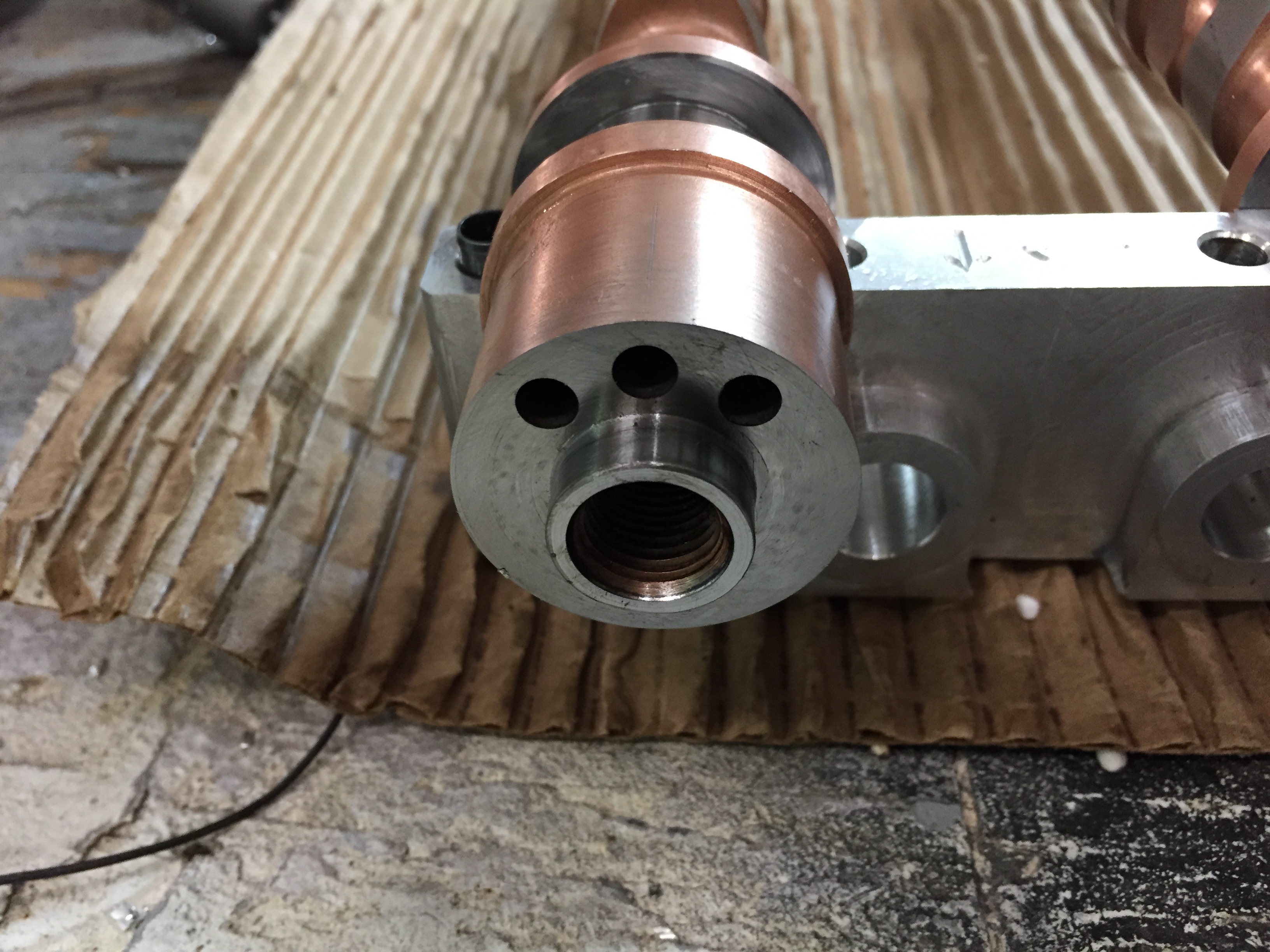
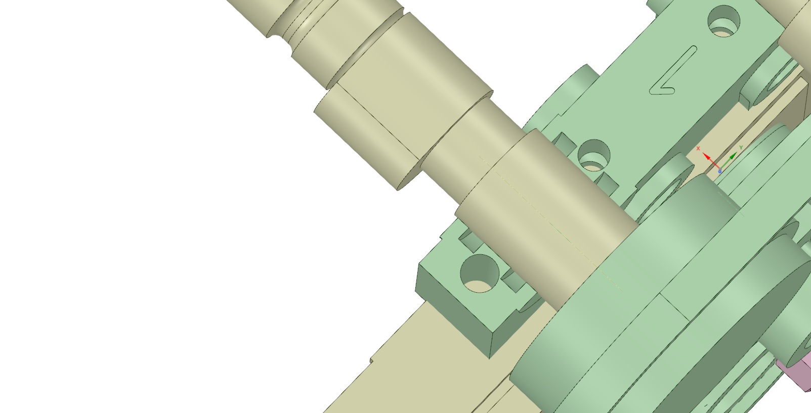
The head has been made wider at the front, the valve cover is 1/2″ higher to accommodate the gears and the timing cover has been redone. It’s wider plus it has a solid section at the bottom front that will become the manifold for the VCT valve. In the above picture you can see the oil inlet valve to the left and then the advance and retard circuits on the head. The Honda exhaust gear gets the center machined out and 6  5mm holes are drilled through. The KA24 idler gear will have the outer gear machined off to match the bore on the Honda gear and 6   5mm holes drilled and tapped to hold the two together.

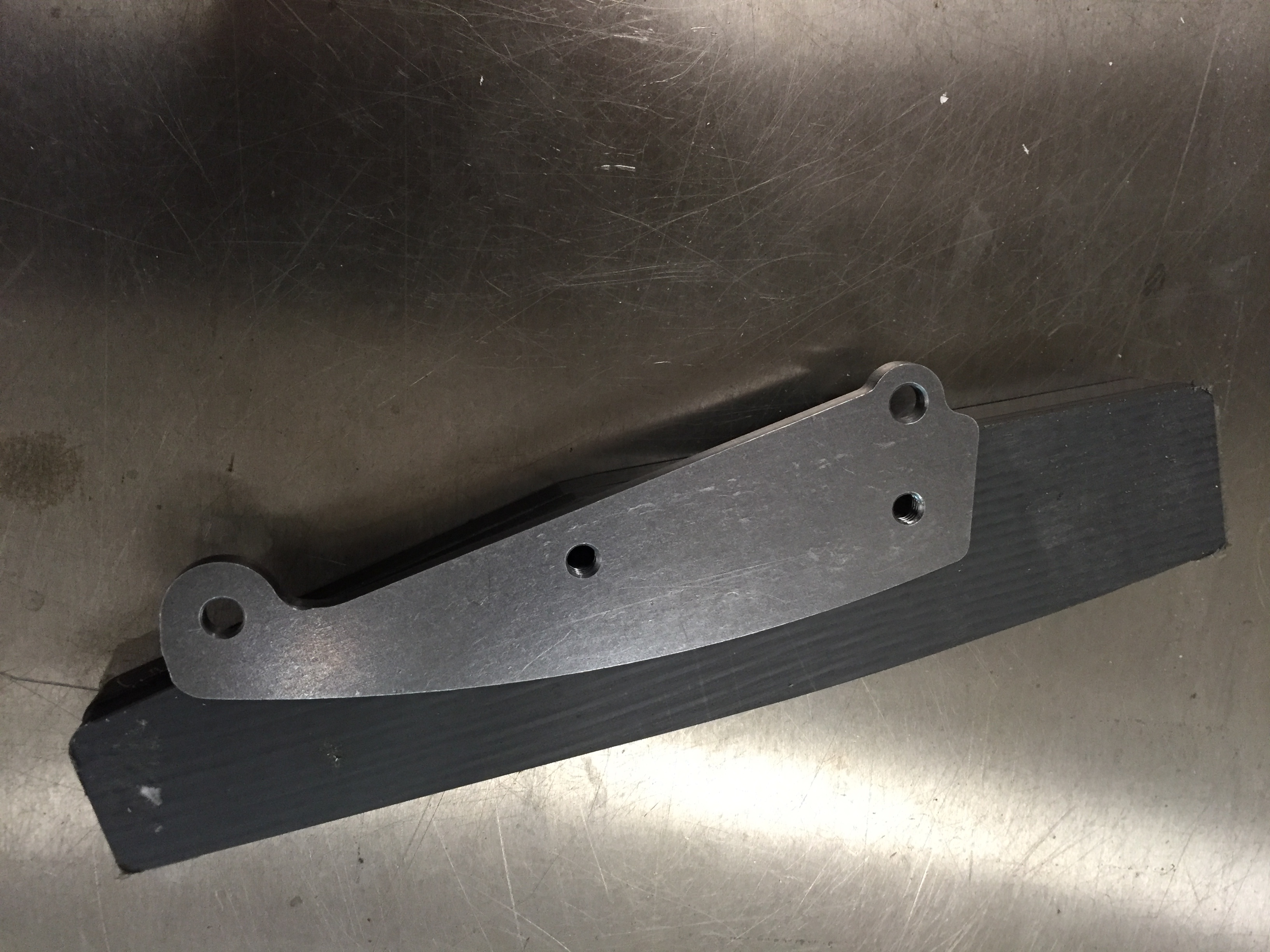
Here is the timing cover and VCT in place.

The VCT is from a V6 Nissan and should work fine as it has the same port sizes as the Honda.

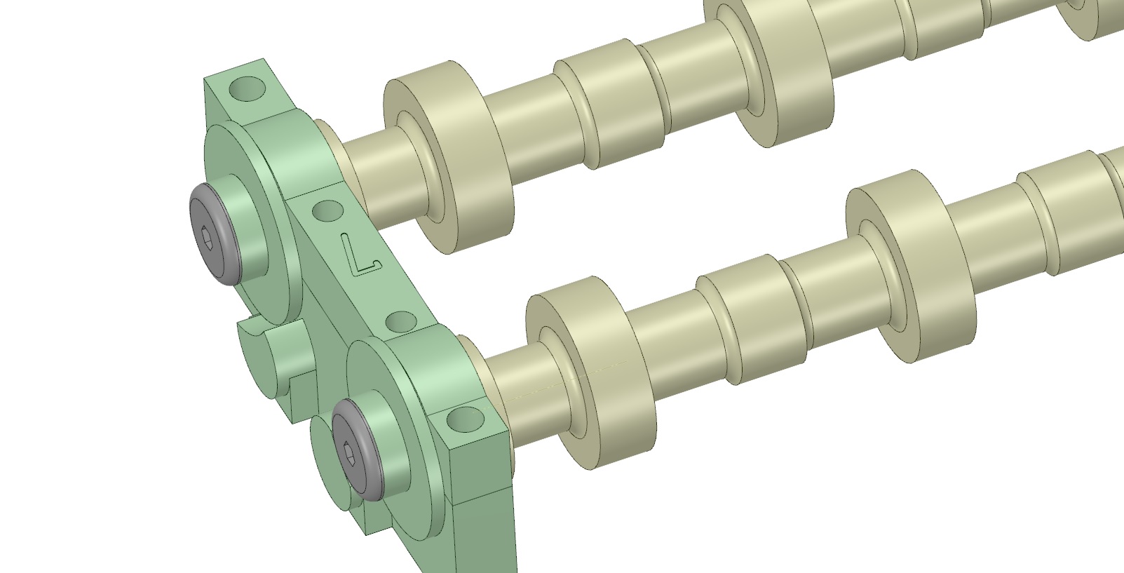
I’ve made the #1 tower wider to accept the grooving for the oil circuit.


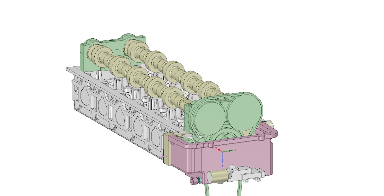
Since VCT and sequential injection require trigger wheels I redesigned the cams and rear tower. This is now the thrust area. It uses the stock Honda washers and bolts. The washers will work for Non VTC but will need to be customized for VCT and or sequential.


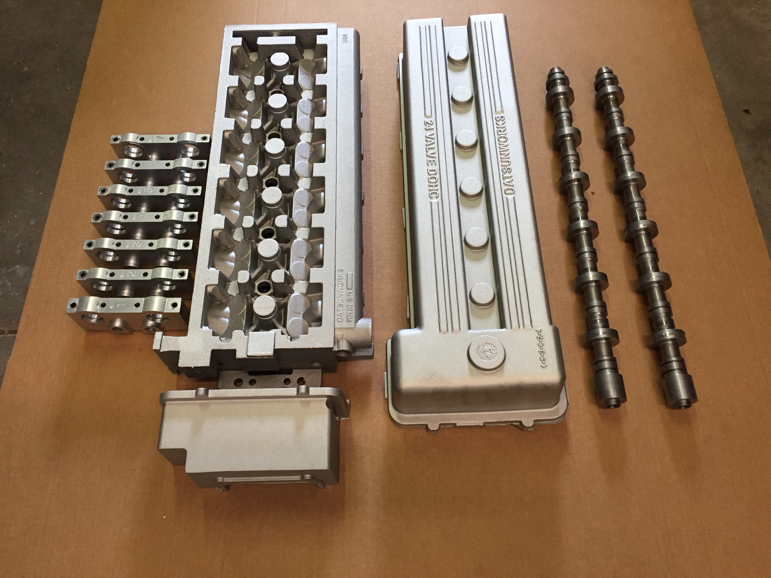
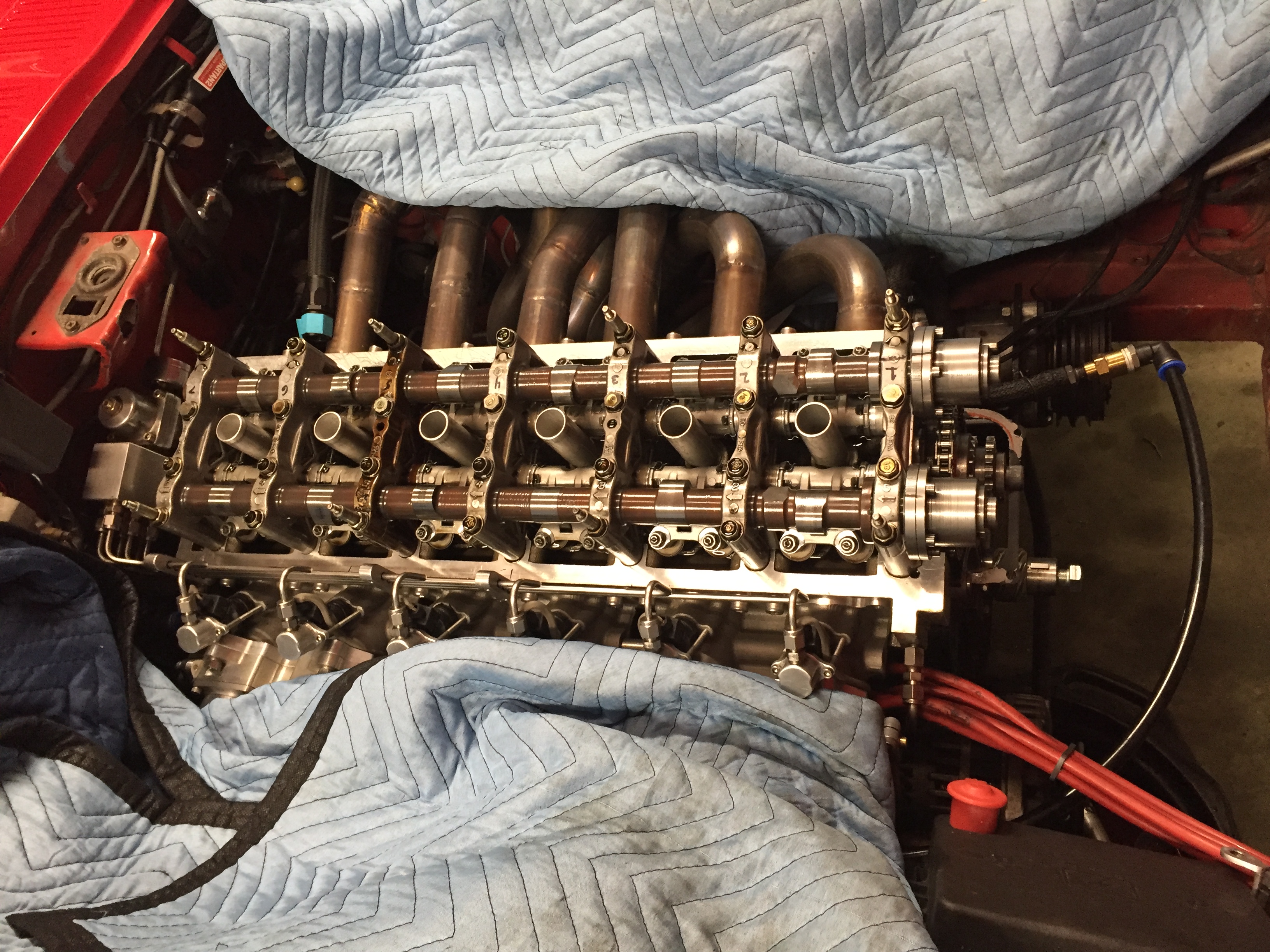
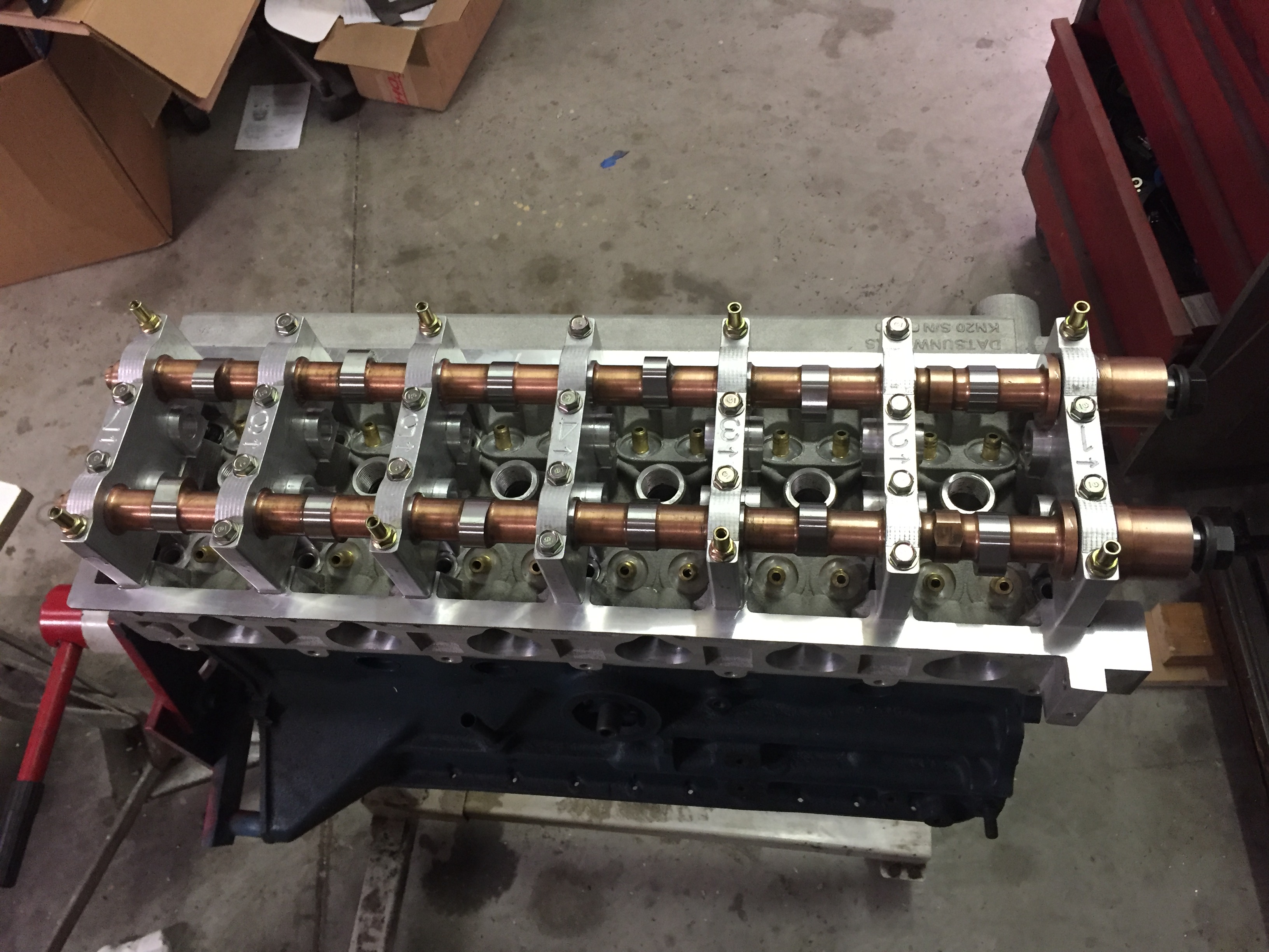
And here it is in all it’s glory.

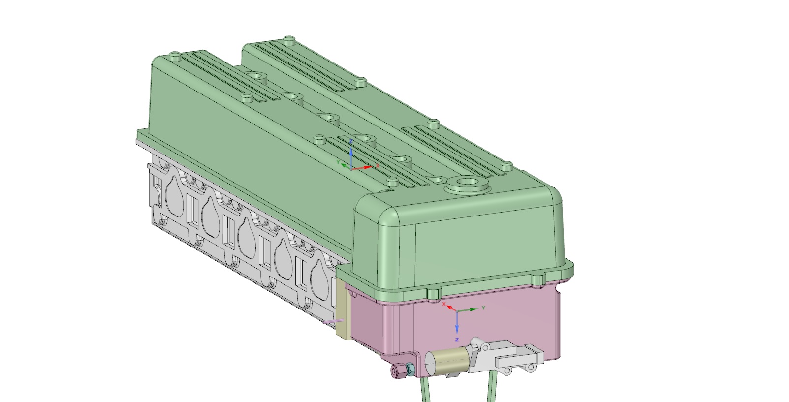
I raised the valve cover up a half inch and then brought the plug valley back down a half inch since it has to be at a certain level. It actually looks better since the relationship between the cam cover and valley is more pronounced.  I added bosses under the valley to accept screws for the the Honda COPs. There are two. One fro the wire pointing forward and one pointing rearward depending how you want it to look.

Now for the nitty gritty.  All of the castings and cam towers are currently sporting these modifications including the one I’m doing now. So I guess that officially makes it V3. The non VTC cam shafts have been redesigned to work with the new towers but still use the KA24 upper timing set. If you want to convert from non VTC to VTC you will need new cams and all the other VTC specific bits.

I have no plans at this time to actually make a running version of this myself. My main goal was to make sure that the parts I’m selling now will work with VTC if someone is brave enough to do it. My best guess is you are going to add 3-4 K by the time you have all of the bits working. There is a lot more to it than what you see here. ECU, sensors, plumbing etc. Not to mention I have no idea if the L6 pump will deliver enough volume to even make it work.


But it will fit on the head:)

Small update

I wasn’t happy with the noise I was getting from the chain with the last setup. The custom guide worked well but the pivoting rail on the tensioner side was really noisy. I tore it all back apart and ended up going with two custom fixed guides and a stock L6 lower tensioner. So far this is the quietist of all the setups so far. I still have a tiny rattle between 2500 and 2800. I’m probably going to live with that for now. The Crane lobes are symmetrically ground and I have been told by multiple sources this can cause some issues with noise.


I also just get these in.

Gun drilled S7 tool steel cam core blanks. I’m switching to S7 for a number of reasons. 8620 cores require a lot of steps and they are case hardened. The biggest problem being I need to have a pretty good idea of lobe specs before they harden them. The S7 is through hardened so that gives me a lot more options production wise.

So this is what my car looks like right now.


Actually it’s part of a scheduled tear down and inspection.  I have around 4200 miles on it. There is some burnishing where the roller meets the lobe. The cam bearing journals are burnished like the used cam towers but no galling.


The main reason for the teardown was to rework the lower timing chain. Ever since I converted it from my first version that used the L6 guides to the second version that used the KA24 guides I’ve had an irritating chain noise at idle. At this point I’m pretty sure it was too much slack in the tensioning system.  I had already decided to try and implement a curved tension rail to help reduce harmonics. After a bit of screwing around I threw in the towel and designed my own.


Here is a shot of the finished piece on V2. It’s made from nylon 66. I found some references to people making custom guides with it on the internet.


I made a steel plate that bolts to the existing rail holes. I inset the plate into the back of the guide for extra strength.

I also pressed in bushings to keep it from crushing and loosening up.
And here’s how many iterations it took to get it the way I wanted.
And that’s how the sausage gets made:)

It’s like Christmas in February!

Cams showed up from Schneider today. Did a test fit and I’m able to spin them by hand. The thrust faces are a hair tight so I’m going to loosen them up a bit. Other than that they feel great. I have to stuff a crank in my mockup motor and then I can get started on the timing chain.

Well it’s back in the barn finally.

Everything looks great and now I can get back on finishing off all of the rest of the stuff. Ran my 1.25″ gauge rod through the towers. A little snug but I’ll wait on the cams to get here before I do any honing.


And naturally I’m super slammed with pattern work right now.

Just uploaded a new video.

Trying out some new microphones. The placement on this video is one in the cabin and one next to the exhaust pipe. The exhaust mike is dominant at this point as you can’t hear the induction noise which in my opinion is the best part:)  It’s a pretty accurate depiction of what’s coming out the back end though. I’ll shoot one with the mikes in the engine bay next. Shifting at about 6800. On the second run I hit the limiter in first. OOps. The camera mount sucks and I need to work on it. If you look closely through the shaking you can see the front of the car lift when the cam comes on.  I drive it this way a lot. I just love the sound of it!


Thanks

Derek


Time for a small update

The head work on V2 is being done at Rebello Racing. I was interested in getting a head in his hands and everything kind of fell into place for that to happen. The only down side was they are always slammed so it’s taken a little longer than I would like. They worked the bowls a bit but other than that it’s basically the same as it was after the new owner smoothed it out. There was no major shape changes. Dave’s opinion is the head as it is now has the capacity to produce in the 420 HP range based on the numbers they got.


He is onboard at this point and will be offering and recommending the head to his customers. He deals with Schneider Cams and the cores are there getting the lobe profiles done.


I know it’s been slow going for while. It’s just amazing how long it takes to get  things like this moving.


I’m attaching the flow sheet he sent me. Dave explained what the various flow scale references mean. I understood it to basically be a setting in the flow bench to make it emulate the bore size more closely. So as a point of reference the intake flow at .5 is 301 CFM after a correction of .680 is applied to the 443 above it.  Rebello also runs his tests at 25″ WC.

Thanks

Derek


dscn07221

Cam cores back from Crane

img_1367

I’ve incorporated the thrust area into the actual cam. The Honda and V1 has a washer that bolts to the cam. This change allowed me to strengthen the front of the cam and also do away with the cam gear adapters.

img_1368

On the front of the cam I had 3 dowel holes drilled. The only way to adjust the cam timing on the K24 is to buy or make modified cam gears with offset dowel holes. The single dowel gives you 2.5 degrees adjustment at the crank per hole. By using three holes I was able to split that to 1.25 degrees advanced and 1.25 degrees retard.  This is a big improvement over V1 with the adjustable hubs.

img_1369


img_1370


The cam is semi finished from Crane. The lobes will be dialed in buy whomever ends up doing the final grind.


img_1371