There are a lot of reasons why I post the good, the bad and the ugly, but mostly because I think it really helps people realize just what goes into creating something that is truly custom. And why custom fabrication is so pricy. Some time ago on HybridZ there was a thread about a hybrid Z car that was being sold for over a hundred grand or thereabouts. It was green just to jog some memories. It kind of settled int those that couldn’t see the value and those that do fabrication that could. I’m being broad with my brush but you get the picture. I took one look at the pictures and immediately saw that kind on money in it.
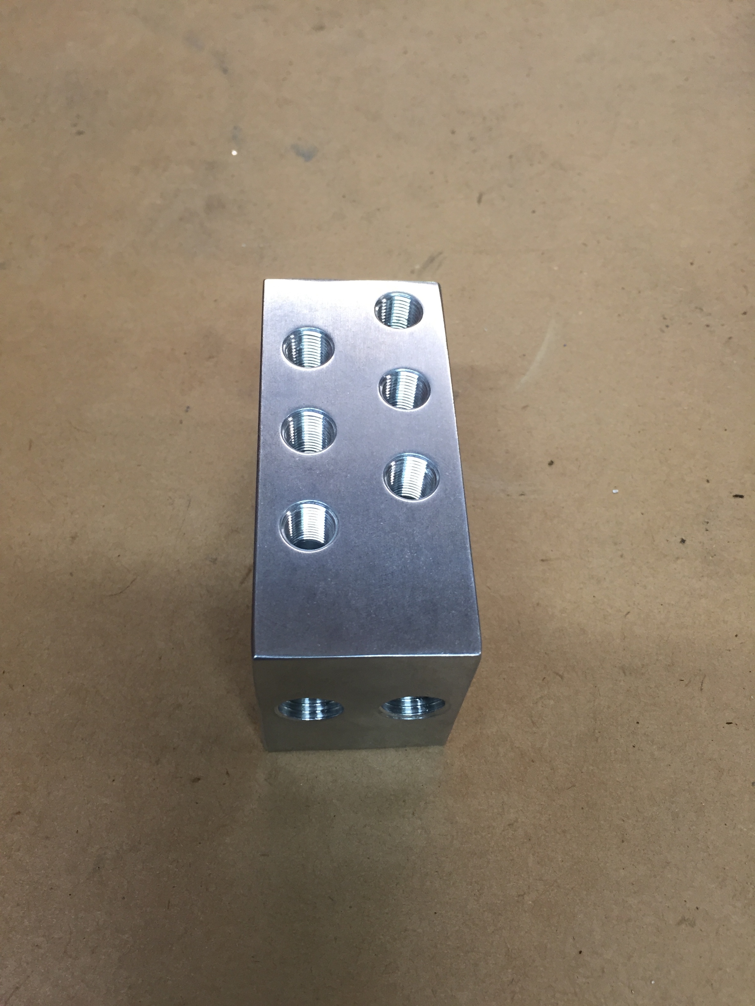
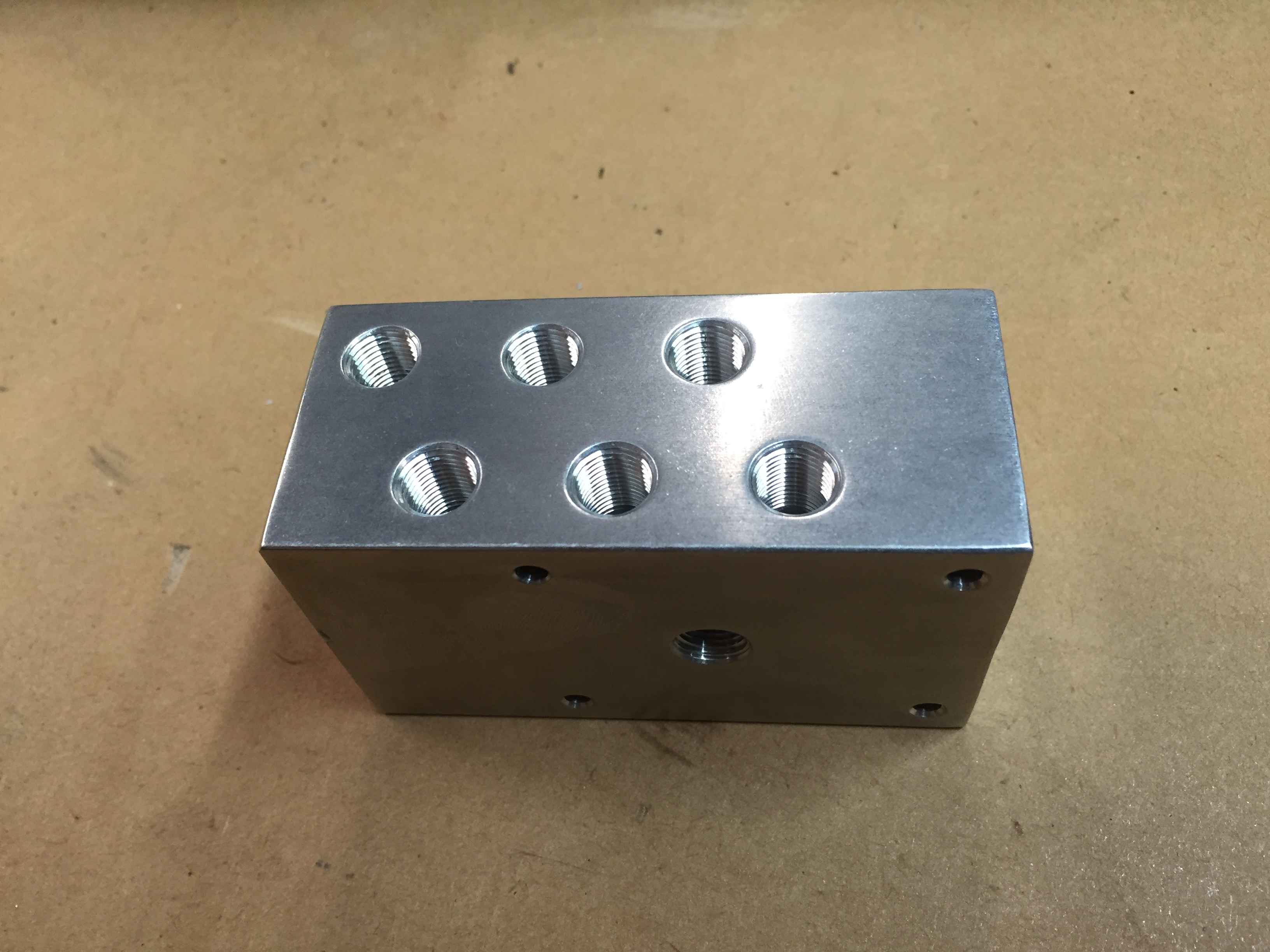
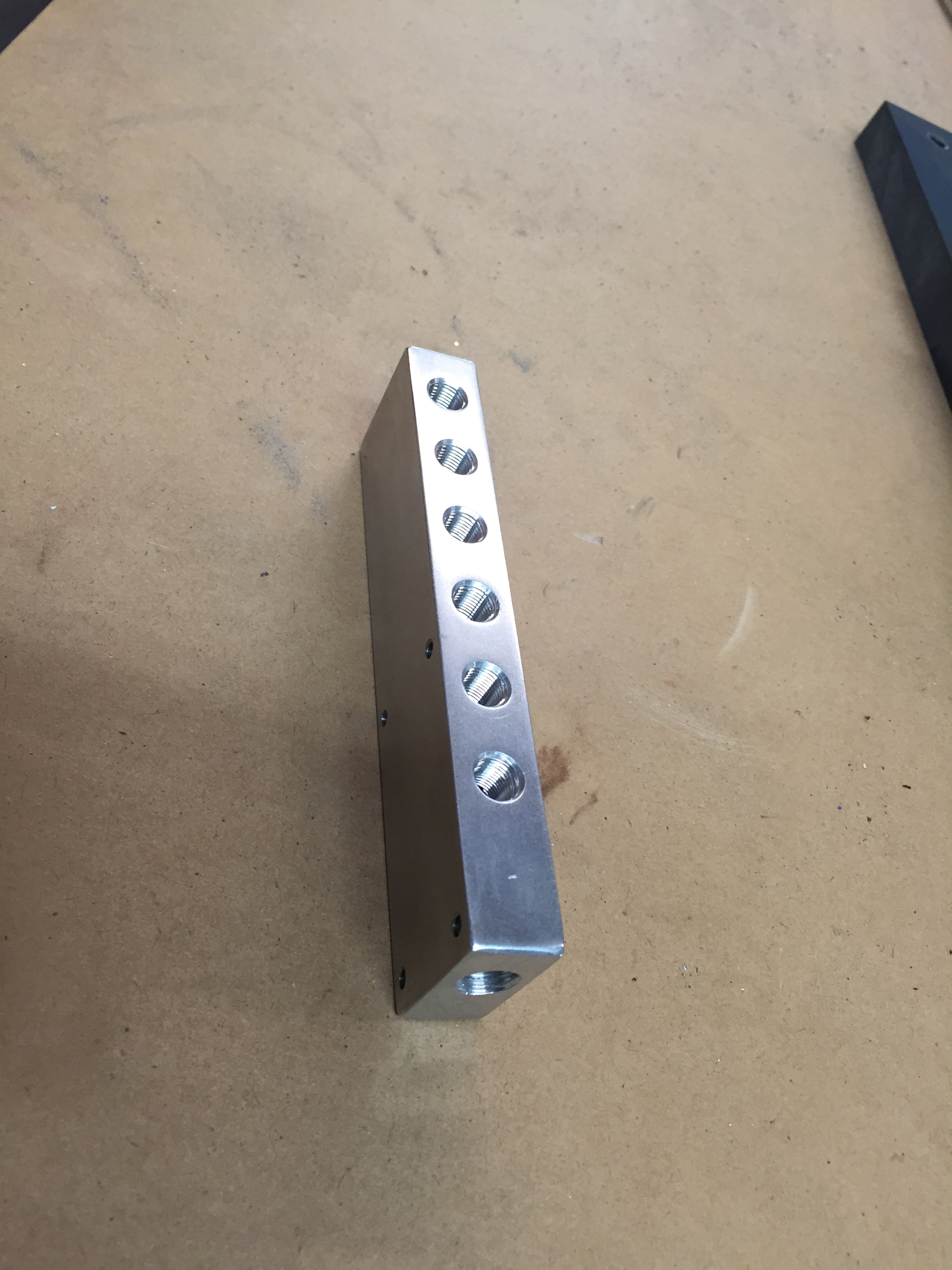
So for this tale I’m the customer and the fabricator. I’m at the point where I want to get going on the fuel system. I made all the injector caps already but I needed a fuel distribution block so I could do the hard lines. I discussed the options with my customer (me) and we settled on a straight block with the fuel lines one on top of the other. Much like the one I already had on my car. I did a 3D model of it which included measuring the space available, measuring the distance required between the fitting in order to get a wrench on them, inlet, outlet and mounting holes. The customer approved the 3D model and I commenced to machine the block. Since there was only one I had to baby sit every operation. No screw ups. I chewed up the better part of a day by the time I was done with everything including finishing. Now if you want my undivided attention for a day it’s going to cost you $400.00 or more. So the piece looked exactly like the 3D model and functioned exactly like it was designed to do. Except the customer (me) just didn’t like the look of it in application. The customer wanted it right so we started over with a new design. Now this one took about half the time since it used all the same general measurements and tool operations so the machine work went much faster.
So here we are with five or six hundred dollars in a simple fuel distribution block.
And that my children is why this crap costs so much:)
First design:
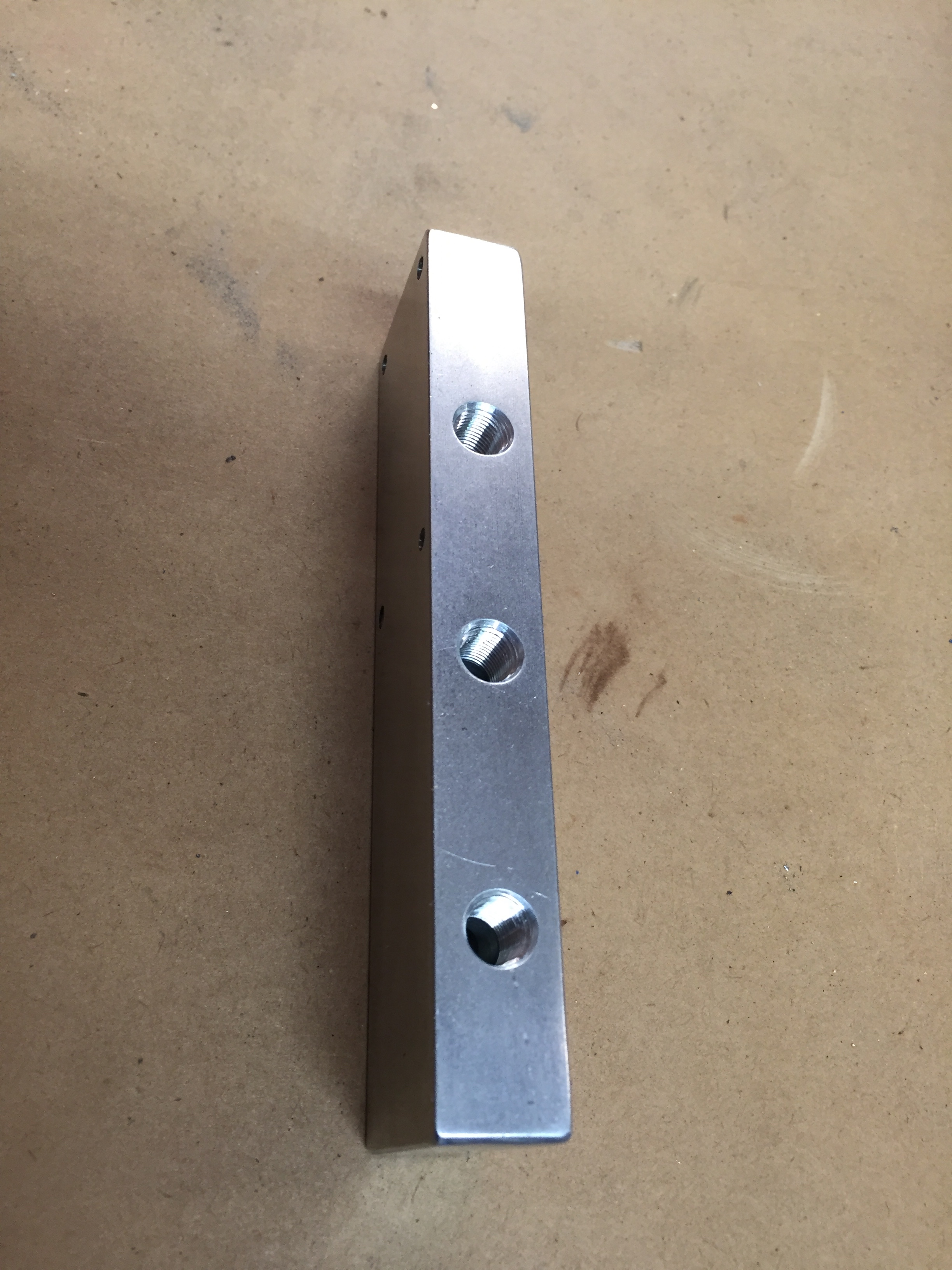
Second design: