As many of you who have followed along for a while know the timing chain arrangement has been my White Whale since the beginning. I knew I wanted to use the KA24 timing chain setup and for the most part I was able to make that work. The problem was there just wasn’t enough room to fit the pivoting slack side guide and have it pivot at the bottom like it’s supposed to. The compromise was to pivot it at the top, use a custom guide and use the bottom tensioner in the stock L6 position. This worked but the custom guide had to be a little thin in one area to clear the lower timing cover. Now here comes a lesson for all you aspiring engineers out there and how solutions to complex problems can be incredibly simple.
I was speaking to Brian at Rebello after he finished the KN20 build they did for Z Car Garage. This was the first build they did for a sub 3.2L and they decided to use my system as opposed to the more complex system they designed for for the 3.5 motors. We were discussing the lack of room on the slack side for the top pivoting guide and he mentioned that the KA24 heads have the idler gear pushed towards the tension side more than I had mine. I agreed this was worth looking into and set about manipulating the 3D model to see what I could make happen. I found I could pick up about 19mm by shoving the idler gear over. On the face of it a very simple solution to increasing the thickness of the pivoting guide. Problem solved. But wait it get’s better.
As I was sitting at my work station shoving various 3D components around to see what was workable I realized a fair amount of room opened up on the top and there may be room to squeeze a tensioner up there and have the bottom pivot guide I always wanted. I contacted Tioga who is my go to person for all things OEM and he got me info on the various available external tensioners that could possibly work. The problem was they were all too big to fit.
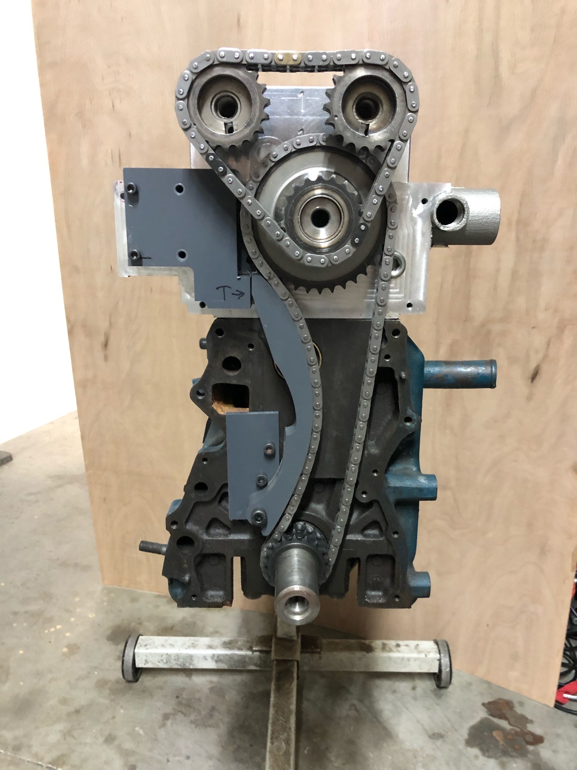
Then the epiphany. Why not design my own tensioner that will fit inside the existing available envelope. Booooooommmm. The hardest part was that I absolutely wanted it to retrofit to the existing heads I already had out there. It was apparent that this would work and fortunately I had a head still here so I set about with my tried and true mockup process. A little CAD/CAM add a little old school analog, bring the analog back to digital, rinse and repeat. I ended up with this mockup. The letter T represents where the tensioner piston is.
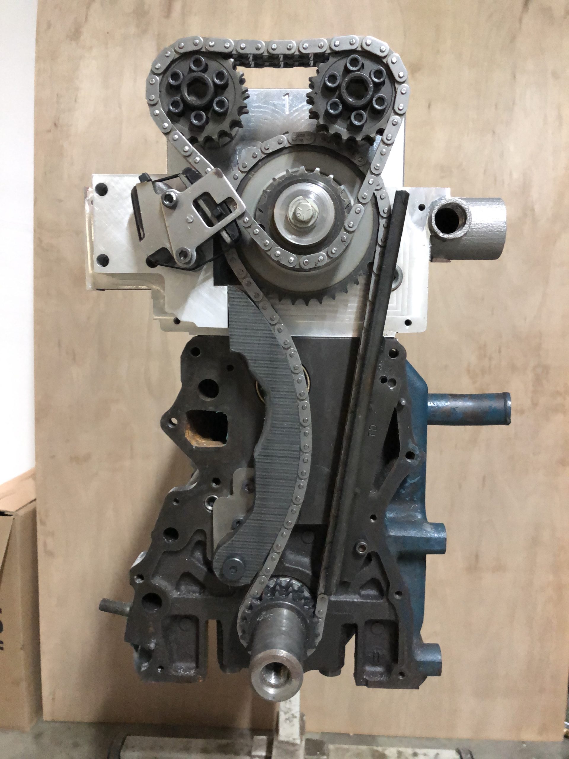
And here is the final product. The adjustable cam sprockets are from Tomei FYI and are really well made. The slack side guide is much more robust and the front lower timing cover fits without any modifications. The stock L6 tension side guide fits with some minor slotting and cutting. The chain angles and flow look great so I’m super happy with the outcome.
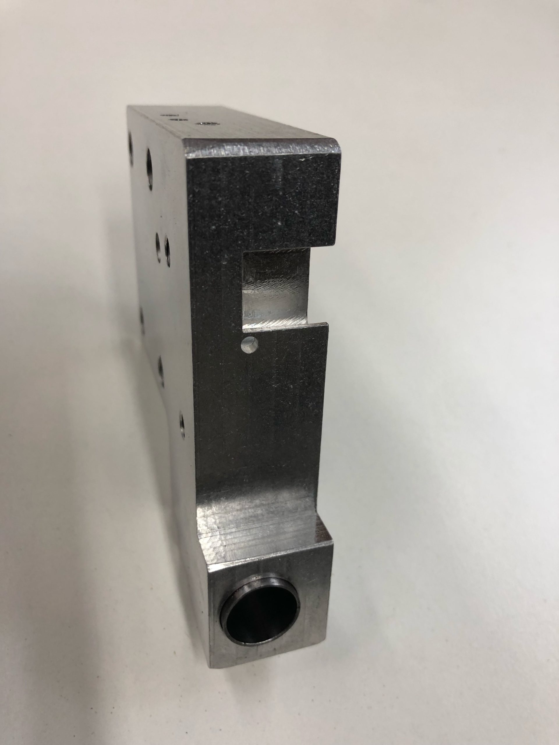
The tensioner is also the mount for the upper tensioner. The slack side tensioner uses the piston, spring, and check valve from a KA24 tensioner. The body is 6061 aluminum with a 4130 DOM (drawn over mandrel) honed sleeve inserted as the cylinder.
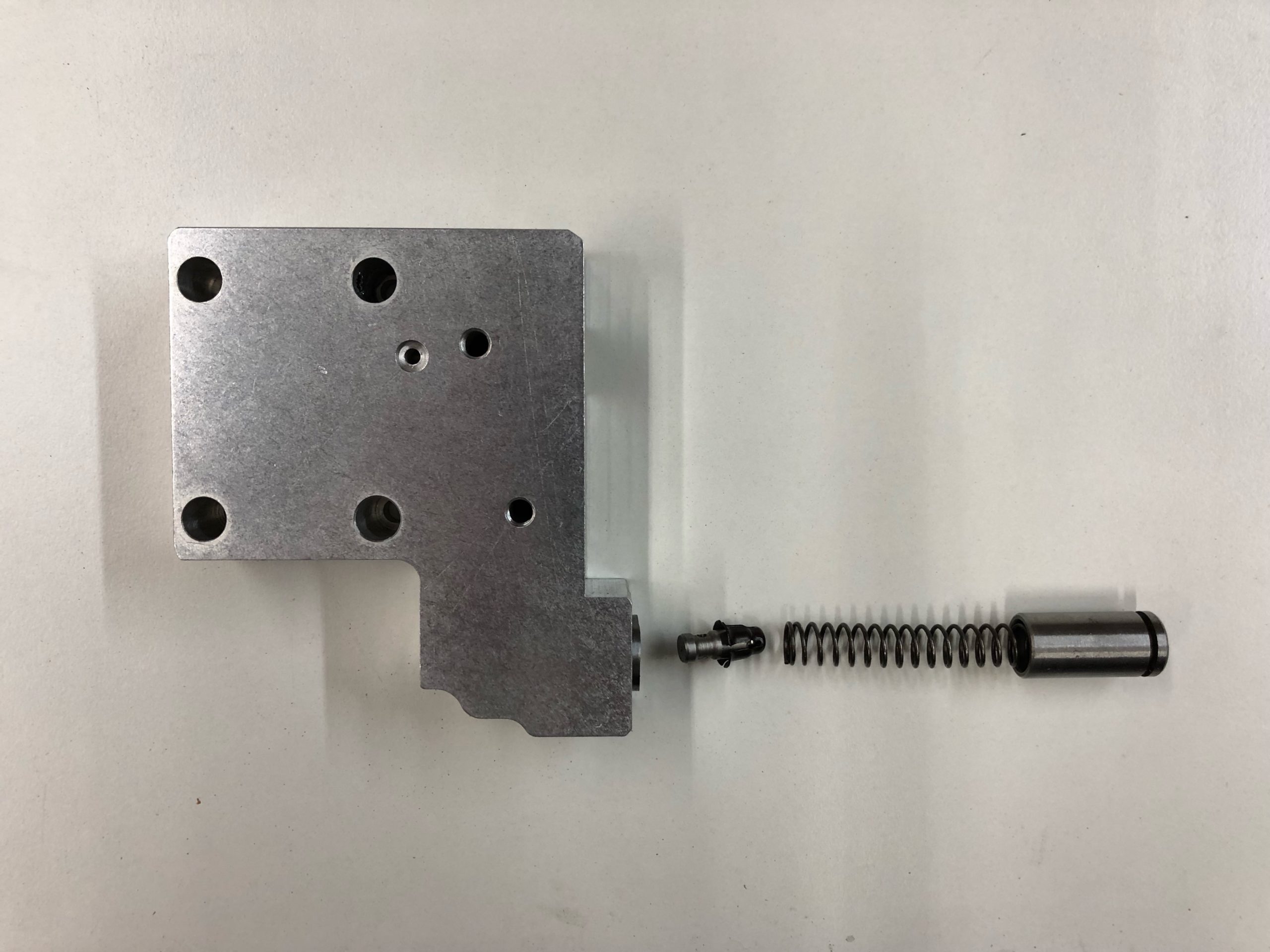
The front of the head has scuppers to drain the oil from the valley and the new tension block blocked the right one. I had to machine a drain into it and decided to include a dribble hole to help oil the lower chain. Probably useless and the KA24 upper tensioner pukes so much oil that I doubt the lower chain will ever run dry but I felt like putting it in.
It feels really good finally making this work and short of any minor changes this is going to be the go to chain system for anyone running a single row lower chain.
I saw Rob , Z car garage drive the head around his test loop and put on his Dyno.
At this point. I……would go to cosworth that’s been building twin Cam heads in small numbers since 1960’s.
Have them produce the head as a complete bolt on.
They have twin Cam heads in their DNA
And manufacture them.
This would reduce all the side parts,machining, ECT.
Have a limited partnership. They produce you sell
No extra costs or work.
Hello I was wondering what the price will be on the finished product of these kits for the Datsun L-Series Motors I currently have a 1976 Datsun 280z.
enjoyed your build, having rebello build an engine for me wish we could put your head on it.maybe later
Thanks
Yea it’s pricy but it looks like it’s coming in at right around 100 HP gain compared to a normal well ported head. At least on Rob’s Dyno. That’s a pretty big jump.
do you have any heads available. maybe we could talk